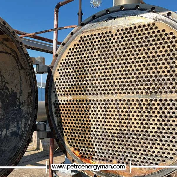
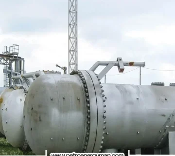
leak in shell and tube heat exchanger does not merely mean fluid loss. This phenomenon can lead to a significant reduction in thermal efficiency and increased operational costs, as the heat transfer rate may decline due to fluid mixing or an inadequate effective heat exchange surface. Moreover, if flammable or toxic fluids are involved, serious safety and environmental hazards arise, including risks of explosion and contamination.
Leakage can also damage downstream equipment and ultimately cause unplanned shutdowns of the entire process. The complex structure of these exchangers, which includes two separate circuits (shell and tube) and limited access to internal tubes, makes troubleshooting a highly specialized and precise task. Therefore, understanding failure mechanisms and employing appropriate leak detection methods is essential to ensure operational stability and safety.
Leak in Shell and Tube Heat Exchanger: Root Cause Analysis
Effective leak detection requires identifying the root causes and mechanisms that lead to failure. These mechanisms often result from mechanical, chemical, and thermal stresses experienced by the exchanger during its operational life.
Corrosion and Erosion
Corrosion is one of the most common causes of failure in heat exchangers. It can manifest in various forms, including pitting corrosion and crevice corrosion. For example, the presence of chloride ions in the fluid can damage the protective layer of stainless steel, leading to sudden and rapid corrosion.
Another destructive factor that often acts synergistically with corrosion is fouling. Fouling refers to the accumulation of unwanted materials such as deposits, polymers, and inorganic salts on heat transfer surfaces, which can impair exchanger performance even in small amounts. This deposit buildup initiates a destructive cause-and-effect chain. As the flow cross-section narrows due to fouling, fluid velocity locally increases in certain areas of the exchanger. This localized velocity increase accelerates metal erosion, removing protective surface layers and exposing the base metal to intensified corrosive attack. This erosion reduces the metal’s resistance to corrosion and sets the stage for corrosion-induced failures. Therefore, fouling should not be viewed solely as a thermal efficiency issue but also as a major contributor to mechanical and chemical failures.
Fatigue and Stress
Leak in Shell and Tube Heat Exchanger often occurs due to thermal and mechanical stresses. Thermal fatigue arises from repeated heating and cooling cycles and significant temperature differences between the shell and tubes, causing physical expansion and contraction.These continuous dimensional changes gradually compromise the integrity of the tube-to-tube-sheet connection, potentially leading to microcracks and, ultimately, leakage.
Mechanical fatigue, on the other hand, occurs due to cyclic loads over time. These repeated loads, even at stress levels below the material’s yield strength, can initiate and propagate microscopic cracks, eventually resulting in complete component failure.
One particularly destructive mechanical phenomenon is water/steam hammer. This occurs due to sudden changes in fluid velocity (e.g., from the rapid closure of a valve), generating a high-pressure wave. This immense force can rupture or collapse the tubes and shell. Additionally, vibrations caused by fluid flow or external sources can exert significant forces on the tubes, leading to failure or loss of sealing.
Manufacturing and Assembly Defects
Defects from manufacturing or assembly processes are also common causes of leakage. These may include physical damage during transport or improper installation, particularly when reinstalling the tube bundle. Sensitive points prone to defects include the tube-to-tube-sheet joint, which can experience roll leaks. Faulty gaskets, washers, or loose bolts and screws are also major contributors to heat exchanger leakage.
Heat Exchanger Leaks: Detection Methods
Shell and tube heat exchanger leak test is a systematic process that begins with visual inspection and continues with pressure and advanced non-destructive testing (NDT) methods.
| Method | Description | Advantages | Disadvantages |
|---|---|---|---|
| Visual Inspection | Checking for cracks, corrosion, erosion, or gasket failure using direct observation and operational data. | Simple, fast, low cost. | Cannot detect internal or microscopic leaks. |
| Hydrostatic Test | Filling one side with water and applying 1.3× working pressure to check for visible leaks or pressure drop. | Safe, verifies structural integrity, widely accepted. | Time-consuming, needs large water volume, may miss tiny leaks. |
| Pneumatic Test | Uses compressed air or nitrogen at 1.1× pressure; leaks found via soap-bubble solution or pressure drop. | Fast, no drying required, detects very small leaks. | High explosion risk, only for special cases. |
| Helium Leak Detection | Injects helium and uses a mass spectrometer to detect microscopic leaks on the low-pressure side. | Extremely accurate, quantifies leak rate, ideal for critical systems. | Expensive equipment and setup required. |
| Fluorescent Dye Penetrant | Tracer dye added to system; leaks glow under UV light for visual detection. | Detects fine surface leaks; easy visualization. | Not suitable for internal or high-temperature areas. |
| Eddy Current Testing (ET) | Electromagnetic probe detects tube wall thinning, corrosion, or cracks. | Non-destructive, fast, ideal for periodic inspection. | Only for conductive materials, needs skilled operator. |
| Ultrasonic Testing (UT) | Uses sound waves to detect subsurface flaws or measure wall thickness. | Accurate depth measurement, detects hidden defects. | Needs access to both sides or good coupling surface. |
| Acoustic Emission Testing (AE) | Detects real-time ultrasonic signals from active cracks or leaks. | Can be used during operation; detects active defects. | Complex analysis, expensive sensors. |
Visual Inspection and Operational Data Analysis
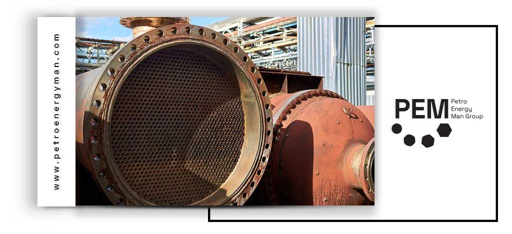
Before any high-pressure testing, the first step is a thorough visual inspection. The inspector should look for signs of physical damage such as cracking, perforation, corrosion, and erosion on the shell, tubes, nozzles, and welded joints. The condition of the foundation, supports, and gaskets should also be examined. Alongside visual inspection, analyzing operational data is highly important. Abnormal pressure drops on the shell or tube side, as well as noticeable reductions in heat transfer efficiency, are early indicators of potential internal leakage or fouling.
Pressure Testing
Pressure tests are the most common and fundamental methods used in shell and tube heat exchanger leak detection, allowing inspectors to identify internal and external leak paths.
Hydrostatic Test
Leak in Shell and Tube Heat Exchanger is commonly detected using a hydrostatic test, which involves completely filling one side of the exchanger (shell or tube) with water and fully venting any air.Pressure is then increased to 1.3 times the maximum operating pressure or at least 1.5 times the design pressure and held for a specified duration (about 30 minutes). During this time, any pressure drop or visible water leakage at suspect points indicates a leak. For shell testing, components such as the shell cover and channel cover are removed, and a test ring is used to apply pressure to the shell. This method allows detection of shell cracks or holes, faulty gaskets, and loose bolts.
Advantages: Due to the incompressibility of the liquid, this method is very safe. The energy stored in water is minimal, so in case of failure, there is no risk of explosion, and the pressure is quickly relieved. Hydrostatic testing also evaluates the overall strength of the component against design pressure.
Disadvantages: This method is time-consuming, requires pumps and large volumes of water, significantly increases the exchanger’s weight, and after testing, complete drainage and drying are necessary. It may also lack sufficient sensitivity to detect very fine leaks.
read more: Plate Heat Exchanger
Pneumatic Test
When water cannot be used, a pneumatic test is employed. In this method, air or an inert gas such as nitrogen is injected into the exchanger, and pressure is increased up to 1.1 times the maximum operating pressure. Leaks are identified using a soap bubble solution applied to suspected points. Precise monitoring of the pressure gauge can also record any pressure drop as evidence of internal or external leakage.
Advantages: This test is quick and easy due to the use of gas, requires no drainage, and, because of the small molecular size of gases, has higher sensitivity for detecting fine leaks compared to hydrostatic testing.
Disadvantages and Risks: Due to the high potential energy stored in compressed gases, this method carries a significant risk of explosion. In case of failure, this energy is released suddenly, which can result in projectile hazards and serious personal or financial damage. Therefore, pneumatic testing should only be conducted in emergency situations and under the strictest safety protocols
Read More: Shell And Tube Heat Exchanger
Tracer-Based Methods
These methods are used to detect leaks that cannot be identified through traditional pressure tests.
Helium Leak Detection
This method is considered the most precise leak detection technique. It works by using helium as an inert, non-toxic, and non-flammable tracer gas. Due to its very small atomic size, helium can easily pass through the tiniest pores. During testing, helium is injected into one side of the exchanger (the higher-pressure side), and any escaping helium molecules are detected on the other side using a mass spectrometer.
This level of precision is essential for critical applications where even microscopic leaks can have catastrophic consequences. For example, in hydrogen-service heat exchangers, the API 660 standard mandates helium leak detection. This method not only confirms the presence of leaks but also measures the exact leakage rate, allowing engineers to predict the remaining life of the exchanger and plan the optimal time for repair or replacement. Required equipment includes a mass spectrometer, vacuum pump, and helium recovery system.
Fluorescent Dye Penetrant
This method involves injecting a tracer liquid containing fluorescent dye into the exchanger fluid (typically oil). After some time, a UV flashlight is used on the external surfaces, revealing the precise leak locations through the glowing dye (usually yellow or green). This method is suitable for detecting very fine leaks and, due to its ease of use, is widely applied in industries such as automotive cooling systems. In some industrial formulations, the dye may also change color upon contact with water or steam.
Advanced Non-Destructive Testing (NDT) Methods
These methods allow inspectors to detect internal tube defects without fully disassembling the heat exchanger.
- Eddy Current Testing (ET): This test uses an electromagnetic probe to induce eddy currents in the tubes. Any defect or wall thinning in the tubes disrupts these currents, which is detected by the device. This method is ideal for periodic and preventive inspection of tubes to identify wall thinning, corrosion, and cracks.
- Ultrasonic Testing (UT): This method sends high-frequency sound waves and analyzes their reflections to detect internal and subsurface defects such as cracks, as well as to measure tube thickness for corrosion monitoring.
- Acoustic Emission Testing (AE): A passive and dynamic method that detects ultrasonic waves generated by internal sources within the material (such as crack propagation or active leaks) as they occur. The main advantage of this method is the ability to perform online monitoring and detect defects while the heat exchanger is in normal operation.
Leak in Shell and Tube Heat Exchanger: Operational Guide
The leak detection process requires strict adherence to operational steps and safety protocols.
Preparation Before Testing
- Isolation: The heat exchanger must be completely disconnected from the main system. This can be done by closing isolation valves or physically separating it from the process lines.
- Fluid Drainage: Both the shell and tube sides must be fully drained and cleared of any fluid.
- Initial Inspection: Before applying any pressure, a thorough visual inspection should be conducted to identify suspicious areas or visible damage.
Leak Test Protocols
- Shell Test: In this procedure, the shell of the heat exchanger is filled with water. Components such as the shell cover and channel cover are opened, and after installing the test ring and performing venting, the exchanger is subjected to hydrostatic pressure. During the test, the inspector observes and records defects such as cracks, holes, or leaks from gaskets.
- Tube Test: This test can be performed separately or in combination with the shell test. In this case, the tube side of the exchanger is pressurized, and leaks at the tube-to-tubesheet connections (roll leaks) or the tube walls are examined.
Safety Protocols for Pressure Testing
It is important to note the fundamental difference in safety hazards between hydrostatic and pneumatic testing. While both involve high pressure, the nature of the test fluid significantly affects the level of risk. Water, due to its incompressibility, stores very little energy. Therefore, in the event of a failure, the pressure is released quickly with minimal hazard.
In contrast, in pneumatic testing, compressed gases such as nitrogen store enormous potential energy. If a defect or failure occurs, this energy is released suddenly, potentially causing explosions or the ejection of parts, posing serious safety and financial risks. For this reason, pneumatic testing is recommended only when the use of water is impossible and must be conducted under the strictest safety protocols, including explosion-proof equipment, precise pressure regulators, and full personal protective equipment (PPE) such as safety glasses, helmets, gloves, and appropriate workwear.
Required Equipment
- Pressure Testing Equipment: Hydrostatic and pneumatic test pumps, calibrated pressure gauges, high-pressure hoses, test rings, and blind plates.
- Tracer-Based Testing Equipment: Helium mass spectrometer for precise leak detection, UV flashlight, and yellow safety glasses for fluorescent leak detection.
- Non-Destructive Testing (NDT) Equipment: Eddy current testing devices with array probes, ultrasonic testing devices with thickness measurement probes, and acoustic emission monitoring systems.
Leak Repair Methods
- Plugging: The most common method for damaged tubes is to block them using plugs. This allows the heat exchanger to continue operating with fewer tubes, though it will result in reduced thermal efficiency.
- Re-Rolling: If the leak originates at the tube-to-tubesheet joint, the connection can be tightened by re-rolling with specialized tools.
- Welding: Where possible, cracks or holes in accessible tubes or areas can be repaired by welding.
If the number of plugged tubes reaches a level where the heat exchanger’s efficiency is significantly compromised, a Retube (complete replacement of the tube bundle) becomes necessary.
Conclusion
Leak in shell and tube heat exchanger occurs due to various factors. Inspectors start with root cause analysis and visual inspections, then perform pressure tests, tracer-based methods, and advanced NDT techniques. Operators must follow strict safety protocols, especially during pneumatic tests. Engineers repair identified leaks by plugging, re-rolling, welding, or retubing to maintain efficiency and ensure operational safety.
No comment