The construction process of a water tube boiler covers all stages from material preparation to full commissioning, with each step explained in detail below.
Heat exchanger cleaning is not merely a routine maintenance task; it serves as a vital lifeline for efficiency in heavy industries. When layers of deposits, coke, or biofilms settle on heat transfer surfaces, your exchanger, instead of facilitating processes, becomes a barrier to energy flow, resulting in fuel wastage and increased stress on pumps.In this article, we take a specialized look at common fouling challenges and examine four advanced cleaning methods, including hydrojetting, pyrolysis, chemical cleaning, and ultrasonic technology. If you are looking to optimize the performance of thermal systems and reduce operational costs, this comprehensive guide will help you select the most precise cleaning strategy.
Importance of Heat Exchanger Cleaning
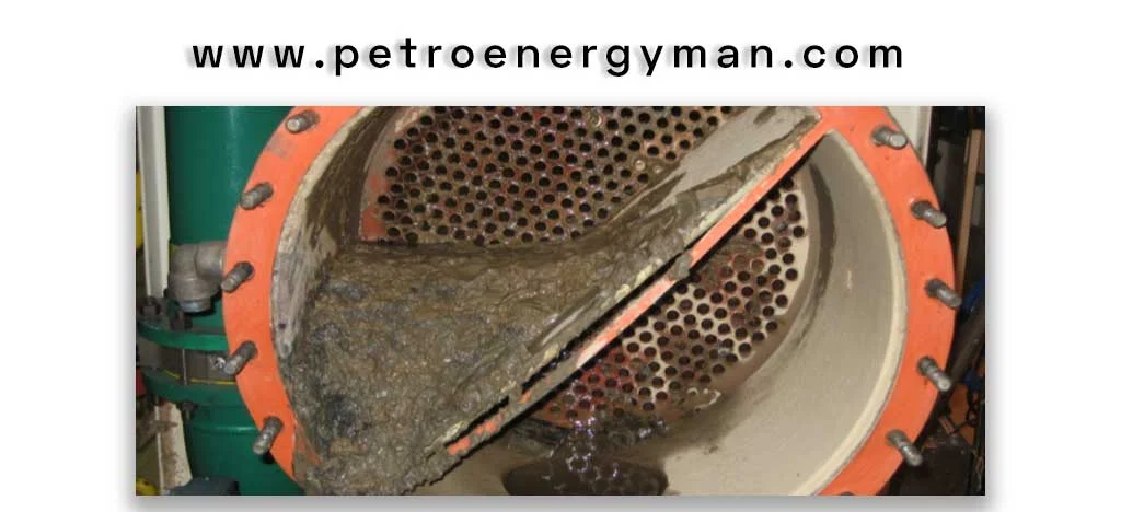
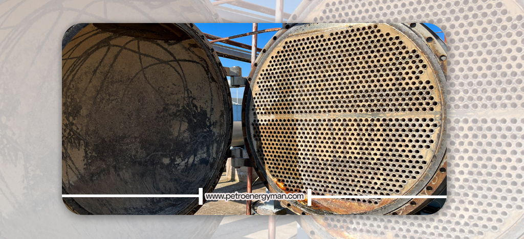
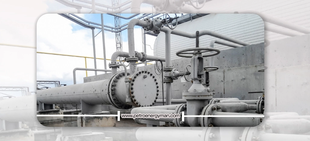
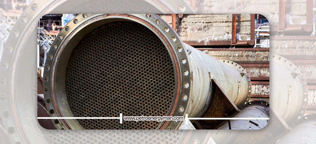
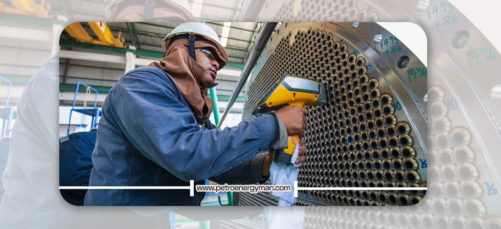
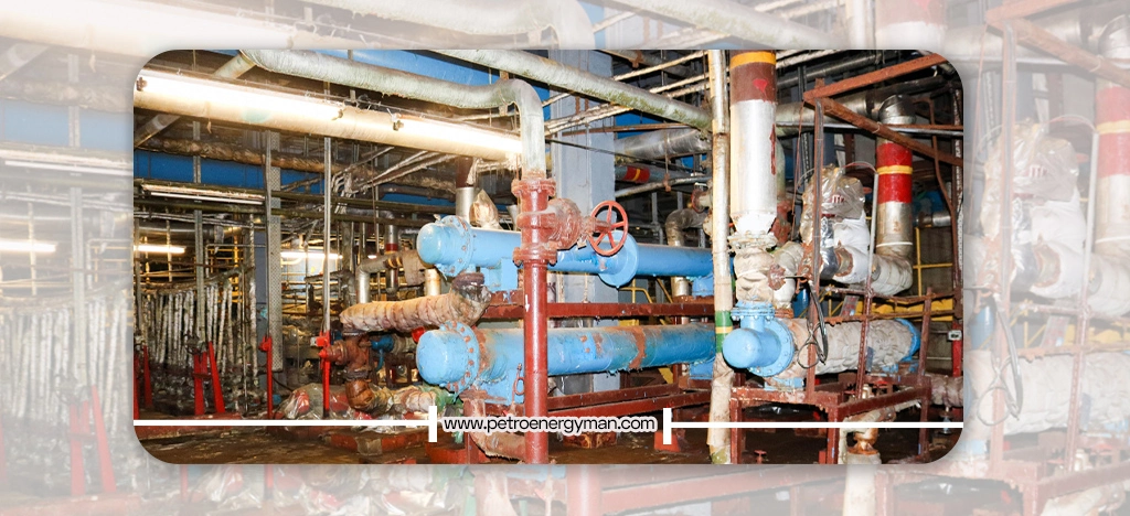
Heat exchanger cleaning is essential because the accumulation of deposits in tubes and components such as boilers, evaporators, and desuperheaters reduces heat transfer efficiency and increases pressure drop. In severe cases, it can even lead to complete blockage. This issue not only decreases the performance of the exchanger but also increases energy consumption for pumping the fluid and raises operational costs.
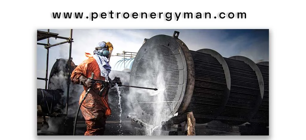
Professional cleaning, especially using high-pressure methods like hydroblasting, allows for rapid and complete removal of deposits while minimizing unexpected downtime. Regular and periodic cleaning helps maintain optimal exchanger performance and enhances the overall system output.
Careful planning of cleaning schedules and selecting the appropriate method are key to extending equipment lifespan and ensuring stable operation across various industries. This approach also prevents unplanned shutdowns. Moreover, research into deposit-resistant materials and advanced monitoring methods enables better management of fouling and reduces operational costs.
Methods of Heat Exchanger Cleaning
Choosing the appropriate method for cleaning heat exchangers depends on the type of deposits, the material of the exchanger, and operational constraints. Below, we explain the four main cleaning methods used for heat exchangers.
High-Pressure Hydrojet or Hydroblasting
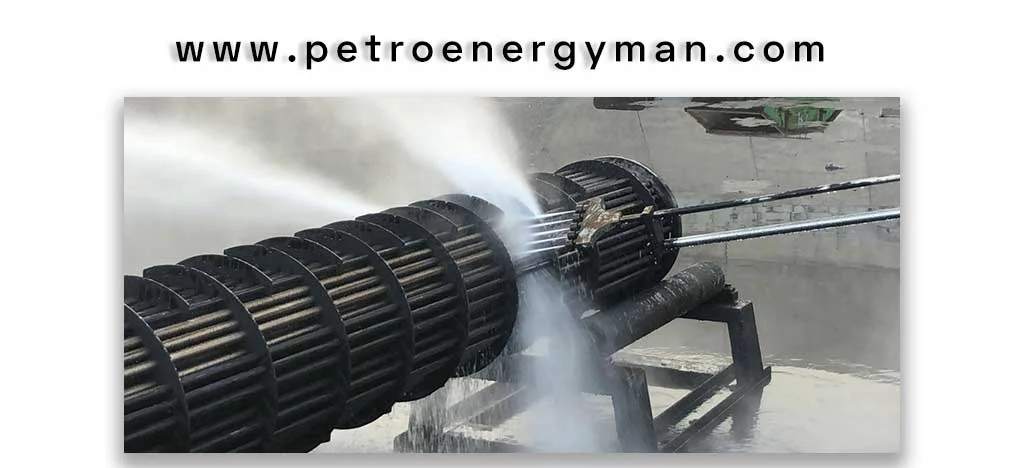
Hydrojetting, also known as industrial water jetting or hydroblasting, is an effective and chemical-free method for removing stubborn deposits and heavy contamination from heat exchanger surfaces. This process involves directing a high-pressure water stream, typically in the range of 10,000 to 40,000 psi, onto the interior of tubes or exchanger plates.
Heat exchanger cleaning with high-pressure water allows the removal of deposits such as metal oxides, sludge, oil residues, and tough organic compounds without damaging the base metal. Key advantages of this method include exceptional cleaning power for adhesive and resilient fouling. Additionally, using water as the cleaning agent is more environmentally friendly and produces minimal chemical waste. The speed of the operation also helps reduce equipment downtime. Engineers and operators must carefully adjust water pressure and select the proper nozzle to prevent erosion or damage to the tube walls.
Thermal Cleaning
Thermal cleaning, sometimes referred to as pyrolysis, is a method used to remove organic deposits from heat exchangers by applying high temperatures. In this process, the heat exchanger or its components are placed in furnaces or specialized equipment capable of providing controlled heat. The high temperature breaks down the structure of organic deposits and oxidizes them, converting them into ash that can be easily removed from the exchanger surface through mechanical cleaning or air blowing.
Heat exchanger cleaning is particularly effective for deposits primarily composed of organic materials, such as polymers, heavy carbon, or coke. Key advantages include a significant reduction in deposit volume to ash and the ability to clean multiple components simultaneously. However, the main challenge in thermal cleaning is precise temperature control to prevent damage to the mechanical properties and metal structure of the exchanger. Excessive heat can cause warping, deformation, or reduced material strength. Therefore, for manufacturers and operators, understanding the material composition and maximum allowable temperature of the exchanger is essential before selecting this method. This technique is less effective for inorganic deposits, such as mineral scales or salts, and may require complementary cleaning methods.
Chemical Cleaning
Chemical cleaning is one of the most common methods for removing a wide range of deposits from heat exchangers. This process involves circulating specific chemical solutions—such as acids, alkalis, detergents, or chelating agents—through the fluid pathways of the exchanger. The chemicals react with the deposits, dissolving them or suspending them for easy flushing.
Industrial heat exchanger cleaning provides a major advantage in its ability to remove complex fouling, including mineral, organic, and biological deposits. This method can reach all areas of the exchanger, even locations with limited physical access, ensuring thorough and comprehensive cleaning. Laboratory tests have confirmed that chemical cleaning can completely eliminate mineral scales and restore heat transfer efficiency to its original state.
However, selecting the correct chemical and formulation based on the type of deposit and material of the exchanger is critical. Using the wrong chemical can result in corrosion or irreversible damage to the equipment. Additionally, proper handling and disposal of chemical waste must comply with environmental regulations to ensure safety and sustainability.
Ultrasonic Cleaning
Industrial heat exchanger cleaning can also be achieved using ultrasonic technology, an advanced and non-contact method that employs high-frequency sound waves (typically between 20 and 400 kHz) to remove deposits and contaminants from heat exchanger surfaces.
The ultrasonic waves propagate through a cleaning liquid—usually water or a mild detergent solution—and create millions of tiny bubbles. These bubbles rapidly expand and collapse, forming a cavitation process that effectively cleans the heat exchanger surface.
The primary advantage of ultrasonic cleaning is its ability to provide deep and uniform cleaning of components. This method is highly effective even on parts with complex shapes, narrow gaps, and areas that are difficult to access. This capability is due to the penetration of ultrasonic waves deep into the materials.
This technique is non-invasive and non-abrasive, so it does not damage sensitive exchanger surfaces. Additionally, its high efficiency reduces the need for strong chemicals, often achieving effective cleaning with just water or mild solutions. This makes ultrasonic cleaning a more environmentally friendly option.
Challenges of Heat Exchanger Cleaning
Limited access to internal surfaces, the hardness and variety of deposits, and the need to minimize production downtime are among the most important factors that engineers must consider to ensure equipment operates in a stable, efficient, and safe manner.
By identifying these challenges, industrial operators can implement tailored cleaning strategies that not only maintain optimal system performance but also reduce operational costs and extend equipment lifespan.
Limited Access and Complex Geometry
Heat exchanger cleaning is particularly challenging because heat exchangers come in various types, including plate, spiral, and finned-tube models. Many of these designs, especially modern ones optimized for maximum heat transfer efficiency, feature complex flow paths, small-diameter tubes, tightly packed fins, or closely spaced plates. These intricate geometries make physical cleaning methods, such as scraping or using handheld water or air jets, very difficult or even impossible. Deposits accumulate in corners, gaps, and dead zones, where direct access is almost impossible. This limited access increases the need for non-invasive or chemical cleaning methods capable of reaching all internal surfaces of the exchanger.
Hardness of Deposits
Heat exchanger cleaning is particularly challenging due to the variety and nature of deposits. Mineral deposits, such as carbonates (e.g., calcium carbonate), silica, metal oxides (e.g., iron oxide), and sulfates, can be extremely hard and adhesive to exchanger walls. Removing them usually requires strong acids or high-pressure mechanical methods.
Organic deposits include greases, oils, polymers, and coke, which form sticky layers and make cleaning difficult. These deposits are typically removed using alkaline solutions or specific solvents.
Biological fouling (biofouling) involves the growth of microorganisms, algae, and bacteria that create biofilm layers, increasing thermal resistance and reducing fluid flow. These types of deposits are removed using biocides and antimicrobial agents.
Selecting the appropriate cleaning method depends heavily on the type and severity of the fouling. Some deposits are so resistant that even strong chemical solutions cannot remove them entirely, and using inappropriate substances can damage the exchanger. Therefore, accurately identifying deposit types and applying suitable cleaning techniques is key to maintaining optimal performance and extending the lifespan of heat exchangers
Extended Production Downtime
Heat exchanger cleaning—whether performed chemically or mechanically—often requires a full or partial production shutdown. Such interruptions reduce output because the plant cannot operate at full capacity or may need to stop the production line entirely. Additionally, labor costs for maintenance personnel, cleaning operations, and material expenses—including chemicals, water, energy, and waste disposal—also increase.
The cleaning process itself is time-consuming; the time needed for cooling, washing, inspection, and reassembling the exchanger can be substantial. For this reason, the development of online cleaning and Clean-in-Place (CIP) methods has become increasingly important. These techniques are designed to minimize downtime while maintaining exchanger performance without a full shutdown. In many industries, optimizing cleaning schedules and managing energy across heat exchanger networks are key strategies to reduce costs and improve operational efficiency.
Conclusion
Modern heat exchanger cleaning represents the intersection of energy cost reduction and equipment longevity. This review highlights how high-pressure hydrojetting addresses tough deposits, thermal cleaning targets organic compounds, chemical processes reach hard-to-access areas, and ultrasonic systems protect sensitive components—each playing a vital role in industrial maintenance.
The significance lies in the fact that well-maintained heat exchangers, by reducing pressure drop and restoring heat transfer efficiency, directly ensure production stability and prevent unexpected downtime, which can impose substantial costs on industrial operations.
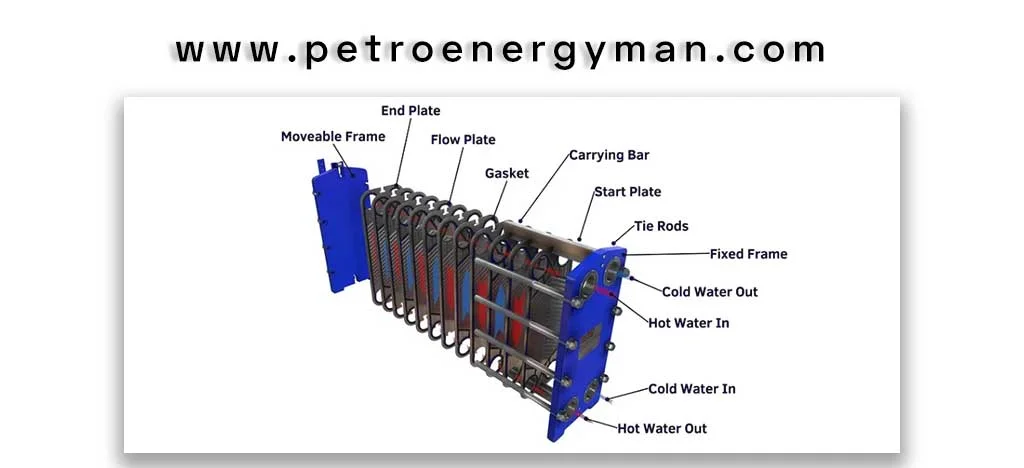
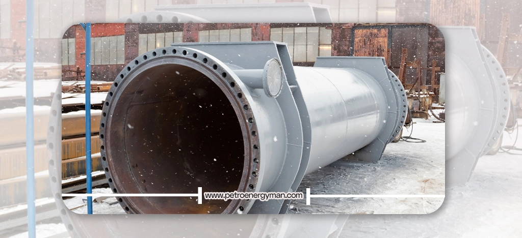
Brazed plate heat exchangers are compact devices designed for heat transfer between two fluids without direct contact, and they have extensive applications across various industries. This text examines their technical structure, performance advantages, materials used, and main application areas. It also details the role of BPHEs in HVAC systems, cooling, energy and utility services, industrial machinery, and refrigeration, including chillers, heat pumps, waste heat recovery, oil cooling, and refrigerated transport systems.
Brazed Plate Heat Exchangers: Technical Overview
Brazed plate heat exchangers are compact devices designed for efficient heat transfer between two fluids without direct contact. These exchangers are constructed from corrugated stainless steel plates, typically AISI 316, which are brazed at contact points using filler metals such as copper or nickel. The result is a fully sealed unit that can withstand high pressures and temperatures without the need for gaskets.
The manufacturing process involves stacking the plates with the filler metal and heating them in a vacuum furnace at around 450°C. This melts the filler, creating strong and durable joints. The design forms two independent fluid circuits, ensuring effective heat transfer. The corrugated pattern of the plates not only increases the heat transfer surface but also directs fluid flow to maximize contact with the plate surfaces, improving thermal efficiency.
The angle of the plate corrugations plays a key role in determining heat transfer rates and pressure drop. This corrugated design optimizes fluid flow, enhances mechanical strength, and allows the use of thinner plates, resulting in more compact exchangers.As a result, BPHEs offer high thermal performance and are ideal for industrial heating systems, refrigeration, and HVAC applications.
Technical Advantages of Brazed Heat Exchangers
Brazed plate heat exchangers, due to their compact design and high thermal efficiency, are considered one of the most efficient types of industrial heat exchanger. By combining operational flexibility with the use of durable materials, these units represent an optimal choice for production processes that face space limitations while requiring maximum heat transfer performance as an operational priority. Ease of maintenance and effective space optimization have given these systems a prominent position in large-scale industrial projects. In the following sections, each of these advantages will be examined in detail from a technical perspective.
Compactness and Space-Saving
Thanks to their engineered, compact design, brazed plate heat exchangers are an excellent choice for applications where space is limited. Their small size and lightweight construction provide significant flexibility in system design and simplify installation. Technical studies show that these exchangers can reduce weight and volume by up to 90% compared to shell-and-tube heat exchangers with similar performance capacity. This optimized footprint not only conserves valuable equipment space but also significantly lowers transportation, handling, and project implementation costs.
Operational Flexibility
Brazed heat exchangers offer exceptional operational flexibility, allowing them to be designed and configured to meet the specific needs of each application. The ability to select different types of connections and adjust the plate pattern enables engineers to tailor the exchanger precisely to operational conditions and required capacity. Additionally, choosing different flow arrangements—such as co-current or counter-current flow—optimizes heat transfer and enhances overall efficiency.
High Thermal Efficiency
These exchangers deliver significantly higher thermal performance compared to shell-and-tube heat exchangers, while occupying up to 75% less space and footprint. This efficiency is achieved through a large heat transfer surface, induced turbulence, and the possibility of counter-current flow design. The compact design allows for a high heat transfer area in a limited space and supports operation under high fluid pressures. The improved thermal efficiency of BPHEs directly reduces energy consumption and enhances heat recovery in industrial processes.
Durable and Optimized Materials
Brazed plate materials ensure the long-term durability and performance of these heat exchangers. The channel plates are typically made from AISI 316 stainless steel, providing excellent corrosion resistance, while pure copper or nickel alloys are used for brazing to create strong and reliable joints.
In specialized applications or environments with aggressive fluids, using all-stainless steel or high-molybdenum alloys such as SMO 254 offers superior corrosion resistance and maintains surface cleanliness. These materials make BPHEs compatible with a wide range of fluids, including mineral and synthetic oils, organic solvents, water, glycol/water mixtures, and various refrigerants.
Maintenance and Serviceability
One of the main advantages of brazed plate heat exchangers is their simple maintenance. The robust, gasket-free structure minimizes the risk of leaks and reduces the need for frequent servicing. The natural turbulence of fluid inside the exchanger helps keep the plates clean, eliminating the need for constant cleaning in many applications. In systems with a high risk of fouling, cleaning-in-place (CIP) methods can be applied to maintain efficiency and extend the exchanger’s service life.
Overall, the combination of compact design, high thermal efficiency, operational flexibility, and durable materials makes brazed plate heat exchangers a highly reliable option for industrial applications. In this context, collaboration with experienced and specialized heat exchanger manufacturers plays a key role in ensuring system performance, as the precise compatibility of the equipment with the type of fluid, operating pressure, and process requirements can only be achieved through such expertise, guaranteeing optimal long-term performance.
Applications of Brazed Plate Heat Exchangers
Brazed plate heat exchangers have key applications across HVAC, energy, and utility systems.
HVAC & Air Conditioning
In air conditioning systems, these units play a central role in temperature management.
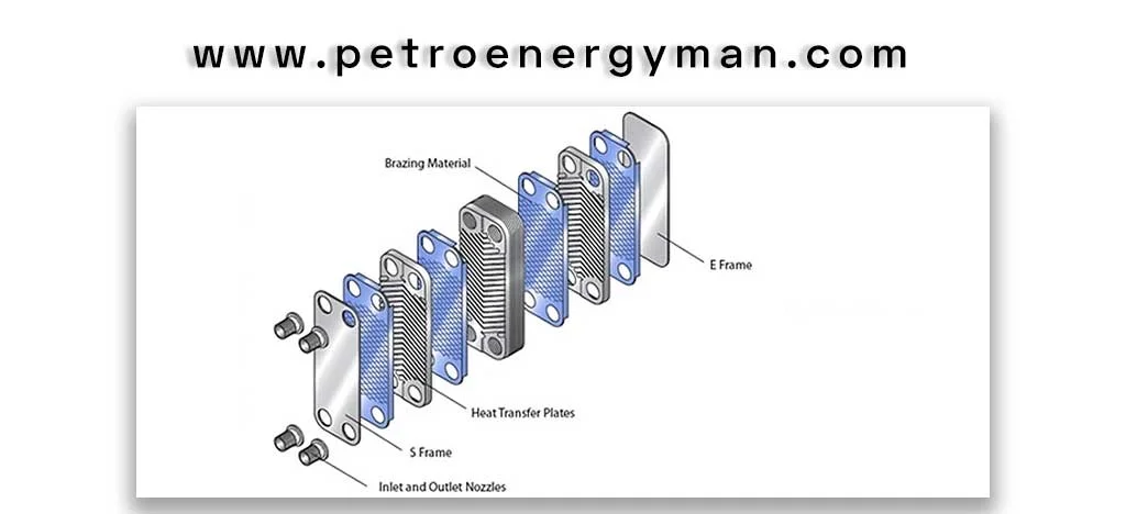
- Industrial and Commercial Chillers: Heat exchanger brazed plate units in industrial and commercial chillers function both as evaporators—absorbing heat from water or process fluids—and as condensers—transferring heat to the environment or cooling towers. Their compact size minimizes chiller installation space, which is especially important in space-constrained industrial environments. High efficiency reduces energy consumption to achieve the desired cooling capacity, lowering operational costs and simplifying compliance with strict energy standards. Optimized channel design and high-pressure tolerance also allow engineers to use low-global-warming-potential (Low-GWP) refrigerants effectively.
- Refrigerated Air Dryers: Brazed plate heat exchangers cool compressed air and condense its moisture. Accurate heat transfer is critical to prevent freezing and maintain low dew points, making them an ideal solution for these systems.
Energy & Utilities
- Heat Pumps: Brazed heat exchanger units in air-to-water or ground-to-water heat pumps transfer heat between a source (ambient air or ground fluid) and building heating systems or domestic hot water. Their ability to achieve low approach temperatures and high efficiency improves the heat pump’s coefficient of performance (COP), resulting in significant energy savings.
- Waste Heat Recovery: Brazed plate heat exchangers are used in waste heat recovery systems, including Organic Rankine Cycles (ORC), to convert excess process heat into useful energy such as electricity or heating. Optimized design and high thermal efficiency allow maximum energy extraction even from low-temperature streams, boosting overall system performance.
- Solar Water Heaters and Boiler Systems: They serve as fluid separators and heat transfer units to domestic or boiler feed water, enhancing system safety, efficiency, and overall equipment performance.
Machinery Equipment
- Hydraulic and Lubrication Oil Cooling: In equipment such as large gearboxes, wind turbines, and plastic injection molding machines, hydraulic and lubrication oils heat up during operation. These heat exchangers cool the oils, preventing oil degradation, reducing component wear, and extending equipment lifespan.
- Laser Welding Machines: Precise and stable cooling of laser sources and sensitive optical components ensures consistent laser beam quality and protects expensive parts from damage.
Refrigeration
- Industrial and Commercial Refrigeration Units: Brazed heat exchanger units in air-to-water or ground-to-water heat pumps transfer heat between a source (ambient air or ground fluid) and building heating systems or domestic hot water. Their ability to achieve low approach temperatures and high efficiency improves the heat pump’s coefficient of performance (COP), resulting in significant energy savings.
- Refrigerated Transport: Limited space and the need to maintain consistent temperatures in trucks and refrigerated containers make these exchangers an ideal choice for cooling systems. Their robust design and high resistance to vibration and shocks ensure stable and reliable operation.
Conclusion
Brazed plate heat exchangers are highly efficient and compact devices used in HVAC systems, energy applications, machinery, and refrigeration. They enable effective heat transfer, reduce energy consumption, and offer easy maintenance. By improving system efficiency and extending equipment lifespan, these exchangers play a key role in enhancing performance and operational savings across various industries.
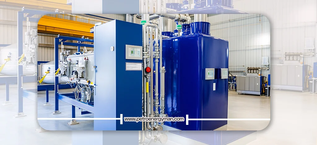
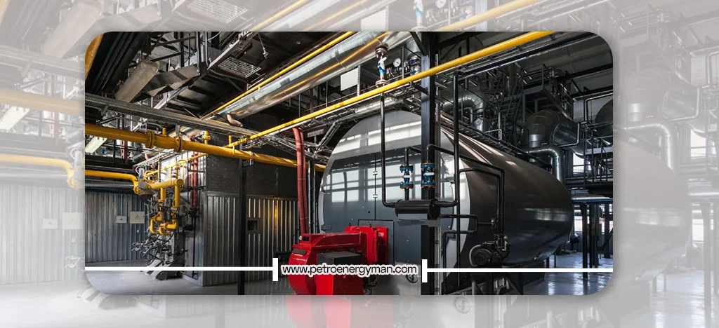
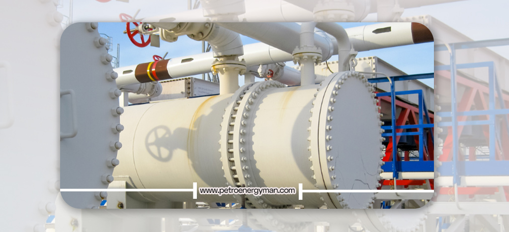
What is a Water-Tube Boiler?
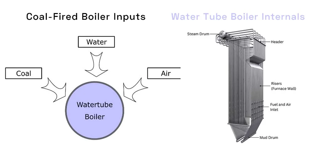
A Water-tube boiler is a type of industrial steam boiler in which water flows inside the tubes while the hot combustion gases pass outside the tubes. As water enters the tubes, it absorbs heat from the combustion gases and is converted into steam. In this system, heat transfer takes place between the cold fluid (water) inside the tubes and the hot fluid (combustion gases) outside the tubes, resulting in the production of steam at high pressure and temperature. The operating pressure range of watertube boiler is typically 10–80 bar, and the temperature range is 180–480 ℃.
Types of Watertube Boilers
Water-tube boilers are designed and manufactured in different configurations to meet spatial limitations, various steam requirements (capacity, pressure, temperature), ease of installation and maintenance, and other customer needs.
| Classification Type | Category | Description |
|---|---|---|
| Working Fluid | Water | Most watertube boilers use water as the working fluid to generate steam. |
| Fuel Type | Single or Multi-fuel | Can operate using natural gas, diesel, or a combination of fuels. |
| Customized Fuels | Can be redesigned to use process gases, hydrogen, or heavy fuels. | |
| Circulation Type | Natural Circulation | Flow is driven by the density difference between water and steam. |
| Forced Circulation | Circulation is maintained using pumps for better flow control. | |
| Structure | O-Type | Dual flue gas paths, balanced weight distribution, used in portable boilers. |
| A-Type | Compact structure with two gas passes, used for limited space setups. | |
| D-Type | Single flue gas path, high efficiency, commonly used in industries. | |
| Application | Package Boiler | Used in factories and industries for process steam; small to medium capacity. |
| Utility / Hanging Boiler | Large boilers used in power plants to generate turbine steam. | |
| HRSG (Heat Recovery Boiler) | Recovers heat from gas turbines or industrial exhaust gases. | |
| Other Classifications | Tube Arrangement | Boilers can have horizontal or vertical tube configurations. |
| Installation Type | Can be modular, skid-mounted, or field-erected. | |
| Design Standard | Manufactured under standards such as ASME or EN 12952. |
Classification Based on Working Fluid
The working fluid of Watertube Boilers is typically water.
Classification Based on Fuel
Conventional watertube may be designed as single-fuel or multi-fuel units, most commonly capable of using natural gas and diesel oil. Petroenergyman also offers redesign solutions for watertube boilers to operate with process gases, hydrogen, and heavier fuels to meet specific customer requirements.
Classification Based on Fluid Circulation
Water circulation in a boiler refers to the driving force that moves the water–steam mixture. This driving force may be natural circulation, created by the density difference between water in the downcomers and risers along with the thermal head. When natural circulation is insufficient, a circulating pump is required, in which case the boiler is referred to as a forced circulation boiler.
Classification Based on Structure
In O and A types, the flue gases exit the furnace located in the center, turn 180 degrees, and are then divided into two streams entering the tube banks. One of the advantages of these designs is better weight distribution, making them suitable for portable boilers.
However, for general industrial applications, these two designs are nearly obsolete, with the D-type being preferred due to its higher thermal efficiency. In D-type boilers, widely used across industries, the entire flue gas flow after leaving the furnace passes into the convective heat transfer section. The advantage of the D-type is the elimination of flow distribution issues across dual paths.
Classification Based on Application
Water-tube boilers can be categorized into three main types:
- Package Boilers
- Hanging (Utility) Boilers
- Heat Recovery Steam Generators (HRSG)
Utility boilers are typically used in power plants to supply steam for turbines, featuring very high capacity and pressure. Package boilers generally have lower capacity and pressure and are mainly intended for internal process steam consumption in industries. HRSG boilers are often employed in gas power plants to recover heat from the hot exhaust gases of gas turbines, but they are also used in other industries to recover energy from high-temperature waste gases. A common feature among all three types is that water flows inside the tubes while hot gases pass around them.
Other Classifications
Beyond the above, water tube boilers may also be classified by tube arrangement, installation method, and construction standards such as EN 12952 or ASME. The diversity in watertube designs allows manufacturers to deliver optimized solutions for specific industrial needs.
Advantages and Disadvantages of Water-Tube Boilers
Watertube boilers offer
significant advantages that make them the ideal choice for many heavy-duty
industrial and power generation applications. However, like any technology,
they also pose challenges, for which petroenergyman provides tailored solutions based
on years of experience in boiler manufacturing.
Advantages of WaterTube Boilers
High pressure and capacity, high steam generation rate, safety under high pressures, high efficiency, ease of maintenance, variety in design and construction, the ability to use different fuels, and controllability are among the advantages of water tube . These advantages will be explained in detail in
High Pressure and Capacity
One of the most important benefits of water tube boilers is their ability to produce steam at very high pressures and capacities. Package water-tube can deliver steam up to 80 bar and 180 t/h, while utility hanging boilers can reach up to 160 bar and capacities well above 180 t/h.
Safety at High Pressures
Unlike fire-tube boilers, which store a large volume of water in a single shell and require strict safety precautions to prevent explosions, water-tube boilers contain smaller volumes of water distributed across multiple tubes. In case of tube rupture, only a small amount of steam and water is released, significantly reducing explosion hazards.
High Efficiency
The design of water-tube boilers enhances heat transfer between hot gases and the working fluid. With proper insulation, thermal efficiency can exceed 92%, translating into lower fuel consumption and reduced operating costs.
Ease of Maintenance
These boilers are designed to provide accessibility for inspection, maintenance, and modifications.
Flexibility in Design and Construction
Flexible tube arrangement and overall configuration
allow the manufacture of boilers optimized for specific industrial
requirements, including spatial constraints. In addition to standard designs,
petroenergyman offers custom redesign services using specialized expertise
Fuel Flexibility
Water tube boilers can operate on a wide range of fuels, including natural gas, heavy fuel oil, solid fuels, biomass, and hydrogen, enabling industries to optimize fuel choices based on availability and cost.
Controllability
These boilers can operate with multiple burners, either independently or in parallel, and are often integrated with Programmable Logic Controllers (PLC) for precise load management and reduced greenhouse gas emissions.
Challenges of Water Tube Boilers
The water-tube boiler has certain drawbacks or challenges, including manufacturing and installation quality requirements, high initial cost, and the need for continuous inspection and monitoring.
Manufacturing and Installation Quality
Due to their complex design, watertube boilers require high-quality raw materials to ensure both thermal conductivity and mechanical strength. Precise fabrication and optimized design are key challenges.
In PetroMen-designed water-tube superheater tubes are commonly manufactured from SA240 T22, while evaporator tubes are made from SA210 A1, providing enhanced heat transfer, higher efficiency, and durability under thermal stress. These material selections may vary depending on project requirements.
Additionally, the large dimensions of watertube make transportation difficult, requiring on-site assembly, which adds to project complexity and scheduling. PetroMen addresses this by applying documented Fabrication, Shipping, and Erection Procedures, along with well-defined schedules to facilitate the process.
High Initial Cost
The complexity of manufacturing, the need for advanced engineering materials, and precision production processes significantly increase the capital investment compared to fire-tube boilers. PetroMen mitigates this by optimizing material use and employing advanced insulation methods, such as Ceramic Fiber, to reduce both capital and operating costs.
Need for Continuous Monitoring and Control
The operation, maintenance, and servicing of these boilers require advanced technical expertise due to their engineering complexity. Personnel must undergo continuous training, and systems must be carefully monitored. For this reason, Petromen boilers are covered by a full warranty for up to two years, during which the company not only provides the necessary operational training but also guarantees boiler performance for up to 200,000 Equivalent Operating Hours (EOH).
Design Principles of Water-Tube Steam Boilers
The design of water-tube steam boilers is a complex and precise engineering process aimed at meeting the specific needs of customers while ensuring safe and efficient operation
Initial Design Steps and Considerations
The design process begins with the collection of initial data regarding the required steam output, outlet steam temperature, and operating system pressure. Based on this information, key parameters such as the approximate dimensions of the boiler, burner capacity, fan capacity, pump power, tanks, and other preliminary specifications are determined. Additionally, the available space for installation and the required footprint of the boiler system are defined. This approach ensures that the boiler delivers the final steam output while meeting the specific operational requirements of each project.
Key Design Parameters
Once the initial requirements are established, designers focus on detailed technical parameters. These include design pressure, design temperature (for various sections such as the shell, tubes, plates, and fins), flue gas inlet temperature, effective radiant surfaces, and minimum thickness requirements for pressure parts (drums, tubes, piping, and tanks).
A critical parameter in water-tube boilers is the Circulation Ratio (CR). This ratio indicates the level of water recirculation in the system to ensure adequate water-to-steam conversion and prevent overheating of the tubes.
Role of Standards and Software
To guarantee safety, reliability, and efficiency, boiler design must comply with internationally recognized codes and standards. The ASME Boiler and Pressure Vessel Code provides practical and safety guidelines for the construction and testing of steam boilers, while NFPA standards (National Fire Protection Association) are applied to mitigate combustion-related hazards. Additional national and international standards may also be applied.
Advanced engineering software such as ANSYS, FireCAD, PPSD, PDMS, EES, SolidWorks, Catia, and AutoCAD are used to facilitate and improve design precision.
Efficiency Enhancements in Design
Various methods are applied during the design stage to increase the overall efficiency of steam boilers. The higher the efficiency, the more steam can be produced with lower fuel consumption and reduced energy losses.
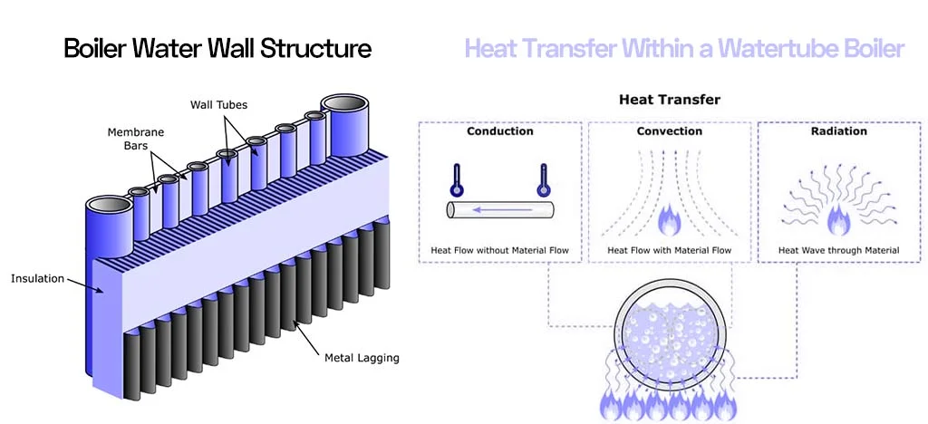
The extensive heat transfer surface area in water-tube boilers—due to water flowing inside tubes surrounded by hot gases—significantly improves efficiency. In general, the efficiency of watertube boilers can reach 92–95%.
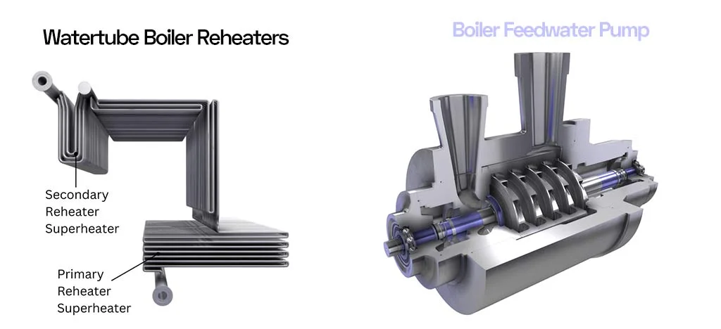
Additional auxiliary equipment such as economizers (for preheating feedwater), superheaters (to increase saturated steam temperature to superheated levels), increased furnace pressure (to improve heat transfer), and deaerators (for removing dissolved gases in water) can further enhance performance. Tube arrangement and layout are also carefully optimized to maximize heat transfer.
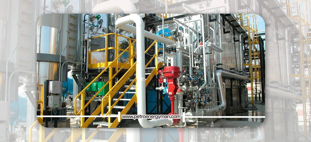
Manufacturing Process of Water-Tube Boilers
Key Fabrication
Processes
- Raw Material Procurement: Main components include seamless alloy steel tubes, steam and water drums (large heavy steel parts), the furnace (combustion chamber), and auxiliary parts such as superheaters, economizers, and control/safety systems, sourced from the highest-quality materials available both domestically and internationally.
- Cutting and Drilling: Steel plates are cut using high-precision CNC cutting machines. Drum drilling is carried out in several stages according to Petromen’s proprietary drilling procedures.
- Rolling and Bending: Cut steel plates are rolled and bent into the required shapes. Water tubes may also undergo bending processes as necessary.
- Main Assembly: Bent and cut steel parts are assembled with high precision.
- Welding: Pressure parts such as drums and joints are welded using automated Submerged Arc Welding (SAW) to ensure maximum weld integrity and quality. Tube-to-drum connections are typically achieved by tube expansion (rolling), and for high-pressure systems or potential tube leaks, seal welding is added. Fin welding on economizer tubes is done with High-Frequency Welding, ensuring metallurgical bonding and improved heat transfer efficiency.
Welders must hold valid certifications according to international standards such as EN287. - Insulation and Cladding: After the structural assembly is complete, the boiler body is insulated with high-grade refractory ceramic fiber insulation to minimize energy losses and improve thermal efficiency.
Quality Control and
Testing
- Weld Inspections: All welds are rigorously inspected by authorized inspectors from the Iranian National Standards Organization using non-destructive testing (NDT) methods such as Radiographic Testing (RT), Ultrasonic Testing (UT), Penetrant Testing (PT), and Visual Testing (VT).
- Hydrostatic Testing (Cold Test): Upon completion, boilers are hydrostatically tested with water at 1.5 times the design pressure to ensure strength and safety under high-pressure conditions.
- Auxiliary Equipment Installation: Essential equipment such as burners, feedwater pumps, water level controls, pressure switches, safety valves, discharge valves, feed valves, and electrical/control panels are installed and tested for proper operation.
- Initial Commissioning (Hot Test): For small-capacity boilers, initial commissioning may be carried out at the factory, but for large-capacity units, it is performed on-site by specialized engineers. In most watertube boilers, hot testing occurs after final installation.
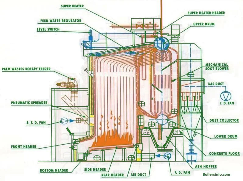
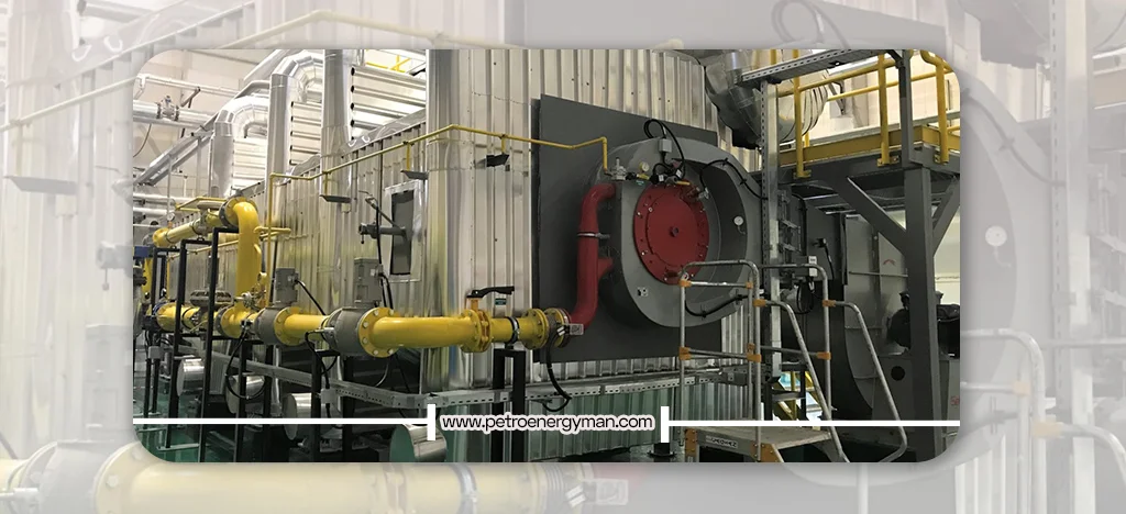
How a Water Tube Boiler Works?
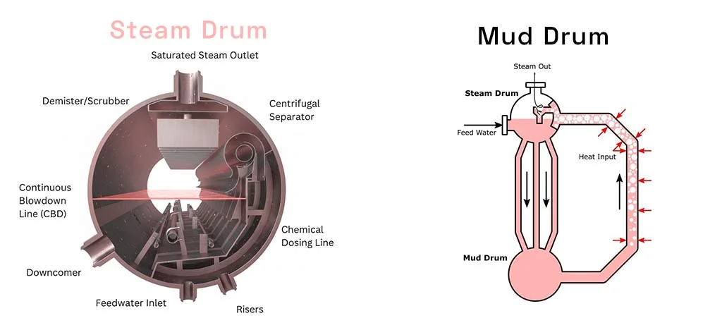
Water-tube boiler: Feedwater, after passing through preheating equipment such as the economizer, enters the boiler drum. From the drum, water flows through downcomer tubes to the heated sections located in the furnace and along the path of hot flue gases. Inside these tubes, water gradually absorbs heat from combustion and transforms into a mixture of water and steam. This mixture, due to its lower density, rises through riser tubes back to the drum. Within the drum, steam separates from the remaining water. The generated steam at the top of the drum is collected, while the leftover water re-enters the circulation cycle. This continuous water and steam circulation forms the basis of stable boiler operation. When dry or superheated steam is required, the steam leaving the drum is directed to the superheater, where its temperature rises and becomes ready for use in turbines or industrial processes. Precise control of pressure, temperature, and water flow ensures fast startup, high safety, and stable performance under varying loads.
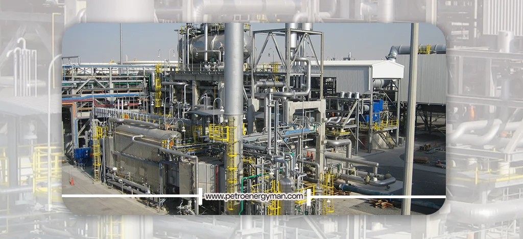
Applications of
Water-Tube Boilers
Watertube boilers, due to their unique ability to generate steam at high pressure and temperature along with excellent thermal efficiency, are widely used in a broad range of heavy industries and critical processes.
Power Generation Plants
Watertube boilers are widely used in thermal and combined-cycle power plants. The steam produced drives steam turbines for electricity generation. These boilers are capable of producing superheated steam at temperatures up to 550 °C and extremely high pressures, which are essential for maximizing turbine efficiency and preventing blade erosion due to water droplets
Oil, Gas, and Petrochemical Industries
These industries require high-pressure, high-capacity steam for heating, separation, chemical reactions, and material transfer. Due to their ability to meet these demands and offer improved safety in hazardous environments, water tube boilers are extensively applied in refineries and petrochemical complexes.
Other Industries
Beyond power and petrochemical sectors, water tube boilers are used in industries with significant steam demand, such as textiles, chemicals, sugar mills, paper mills, leather and rubber manufacturing, packaging, and more.
Capacity of Water-Tube
Boilers
The capacity refers to the maximum amount of steam a boiler can generate within a given time (commonly measured in kg/hr or lb/hr). Package water tube boilers typically range from 5 tons/hour up to 180 tons/hour, while utility (hanging) boilers exceed 180 tons/hour. Proper capacity selection depends on consumer requirements and the cumulative steam demand of all downstream equipment.
Operating Pressure of
Water-Tube Boilers
Designed specifically for high-pressure service, watertube convert water into steam within tubes under extreme pressures while minimizing explosion risks due to reduced water volume. Package types typically operate in the 10–80 bar range (up to ~100 bar), while utility boilers can produce steam at pressures as high as 160 bar.
Steam Temperature in
WaterTube Boiler
These boilers can produce both saturated and superheated steam. Package water tube commonly deliver steam at temperatures up to 500 °C, whereas utility boilers achieve superheated steam at temperatures up to 550 °C.
Water Circulation in
Water Tube Boilers
Efficient water circulation is vital, since not all water within tubes is fully converted to steam. The purpose is to recycle un-evaporated water back into the heating cycle, ensuring higher steam production while preventing thermal stresses and tube damage.
- Natural Circulation: Driven by density differences between hot (lighter) and cold (heavier) water, effective at low pressures.
- Forced Circulation: At higher pressures, the density difference decreases, making natural circulation ineffective. In such cases, feedwater pumps force circulation to ensure adequate steam generation and tube protection.
Conclusion
Water-Tube Boiler, with their ability to deliver high-pressure steam, excellent efficiency, and superior safety, play a critical role in heavy industries and modern power plants. Their diverse design options allow customization to meet specific industrial requirements.
Although they involve higher initial investment costs, their operational benefits make them a justifiable and strategic long-term investment. The future of watertube boiler technology lies in further efficiency improvements, emissions reduction, adoption of alternative fuels (such as hydrogen, biomass, and renewable-based fuels), and expanded automation systems—all of which will continue to reinforce their importance in industrial energy supply.
Water Tube Boiler Mountings are essential for the safe and efficient operation of steam boilers. In this article, we cover key Boiler mountings including steam stop valves, safety valves, feed water regulators, pressure gauges, blowdown valves, level indicators, air release valves, and TDS sensors.You will learn how each component helps control water and steam levels, protect the boiler from overpressure or contamination, and ensure smooth operation.
Water Tube Boiler Mountings
Explore the essential mountings that keep water tube boilers safe and efficient: Main Steam Stop Valve, Auxiliary Steam Stop Valve, Boiler Safety Valve, Steam Drum Level Gauge Glass, Air Release Valve, Feed Check and Control Valve, Pressure Gauge Connection, Boiler Blowdown Valve, Scum Blowdown Valve, Sampling Connection, Low-Level Alarm, Soot Blowers, Automatic Feed Water Regulator, Manhole, and TDS Sensor and Probe.Learn more about the role of each mounting in maintaining boiler performance and safety.
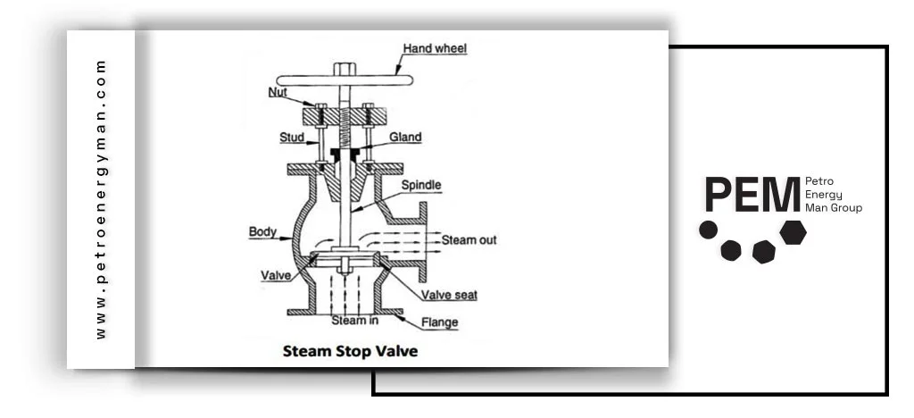
Main Steam Stop Valve
Water Tube Boiler Mountings include the main steam stop valve, which is installed between the main steam line and the distribution header. Its primary function is to allow or stop the flow of steam from the boiler to the steam pipeline, or from the steam line to the consumption process. When open, it directs the generated steam into the main steam line, and when closed, it completely isolates the boiler from the steam system. This valve is typically mounted close to the boiler and must always be operated either fully open or fully closed, never partly open for throttling. In multi-boiler installations, an additional isolating valve must be installed in series with the main valve, and at least one of these valves should be lockable in the closed position. Main steam stop valves are usually globe-type valves with an angular flow path.
Auxiliary Steam Stop Valve
The auxiliary steam stop valve controls the flow of steam to auxiliary steam lines. It is essentially a smaller version of the main steam stop valve and is designed to isolate the boiler from secondary systems. This valve is often manufactured as a check valve to prevent backflow of steam into the boiler in case of malfunction or system failure. It is normally installed directly on the boiler outlet and plays an important role in the safe and reliable operation of auxiliary steam lines.
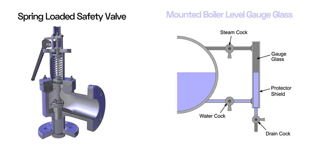
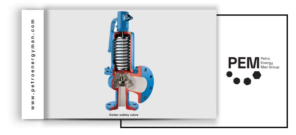
Boiler Safety Valve
Water Tube Boiler Accessories include the boiler safety valve, which is one of the essential components designed to protect the boiler from excessive pressure and prevent potential damage. The primary function of this valve is to automatically release steam whenever the generated steam pressure rises above the allowable limit.
Safety valves are typically installed in pairs: a main valve and a backup valve that is set to open at a slightly higher pressure. This ensures the boiler remains protected even if the main valve fails. The opening pressure of these valves is adjusted and sealed in the presence of an authorized inspector so that no one can tamper with the settings. Safety valves play a vital role in preventing dangerous pressure buildup in steam systems.
Boiler Steam Drum Level Gauge Glass
The steam drum level gauge glass, also known as the water level indicator, is usually installed in pairs to allow manual monitoring of the water level inside the boiler steam drum. These gauge glasses visually display the water level and protect the boiler from potential damage, as low water levels and excessive temperatures can cause severe failures.
The design and construction of gauge glasses are based on the boiler’s working pressure. They are installed such that their lowest visible point is at least 50 mm above the critical water level to prevent overheating. These glasses must be inspected and tested daily to ensure proper operation and to maintain personnel safety against possible hazards.
Air Release Valve or Boiler Vent
Water Tube Boiler Mountings include the air release valve, which is typically installed on headers and drums to protect the system from damage. This valve prevents sudden vacuum formation in the boiler during pressure drops or rapid steam pressure increases and allows air to escape when filling the steam drum or during steam generation. It can also return excess air into the boiler during venting.
Air release valves are usually installed at the highest points of the system, where air tends to accumulate. They are responsible for removing non-condensable gases such as air, which have no thermal value and can impair the performance of the steam plant by covering heat transfer surfaces or causing corrosion in the condensate system.

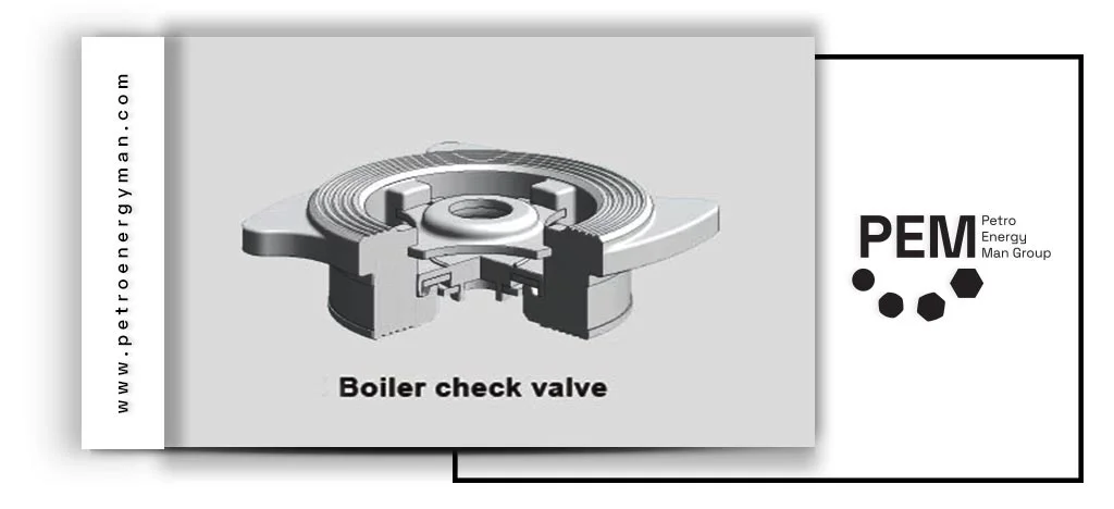
Feed Check and Control Valve
The feed check valve is designed to control the flow of water from the feed pump to the boiler and prevent backflow from the boiler to the pump. This valve ensures one-way flow and is often installed in pairs: a main valve and an auxiliary valve. The main valve is installed in an accessible position to facilitate operation.
These valves often feature a visual indicator showing whether they are open or closed. Using two feed check valves provides double isolation for the feed line, enhancing operational safety and reliability.
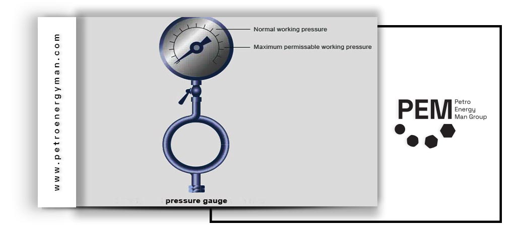
Pressure Gauge Connection
Boiler mountings include a pressure gauge, which every steam generator should be equipped with, typically a simple gauge conforming to EN 12953 standards. Pressure gauges continuously display the pressure inside the boiler and can be connected to the steam space, water column, or steam connection of the boiler. To protect the gauge mechanism from high temperatures, a siphon or equivalent device is often used.
The display should have a minimum diameter of 150 mm and indicate both the normal operating pressure and the maximum allowable working pressure.
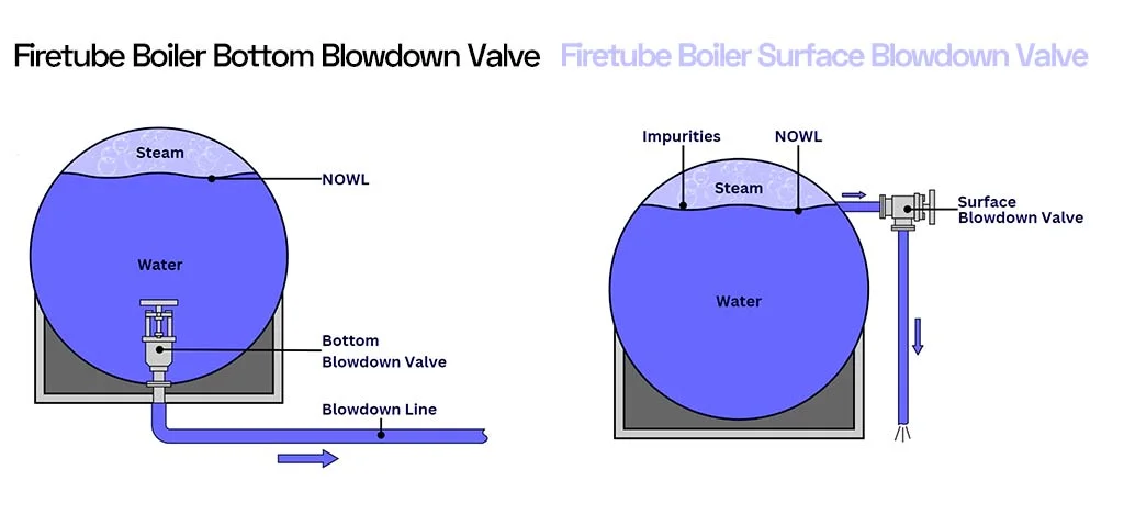
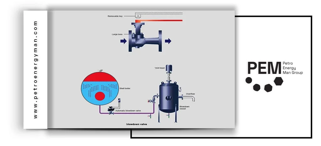
Boiler Blowdown Valve
Boiler mountings also include the boiler blowdown valve, which is used to remove sludge, sediment, and other impurities from the bottom of the water drum. This process, known as blowdown, is essential for maintaining boiler water parameters within acceptable limits, minimizing issues such as scaling, corrosion, and the transport of solid particles.
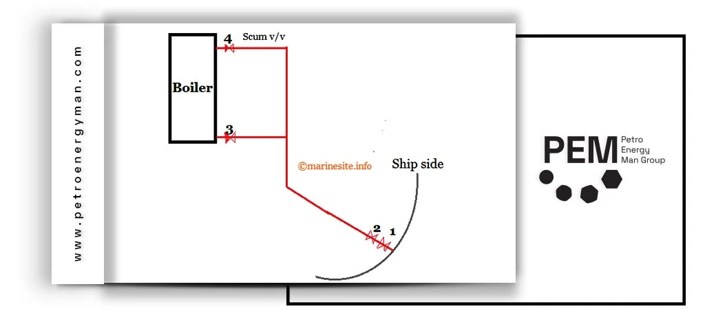
Scum Blowdown Valve
Water Tube Boiler Mountings include the scum blowdown valve, which is designed to remove floating impurities, surface oils, and other scum formed on the water surface. This valve usually features a shallow chamber installed at the water surface, allowing the collection and discharge of floating materials. The scum blowdown valve helps clean the water surface from oily layers or foam caused by agitation or contamination, playing an important role in improving boiler water quality and enhancing system efficiency.
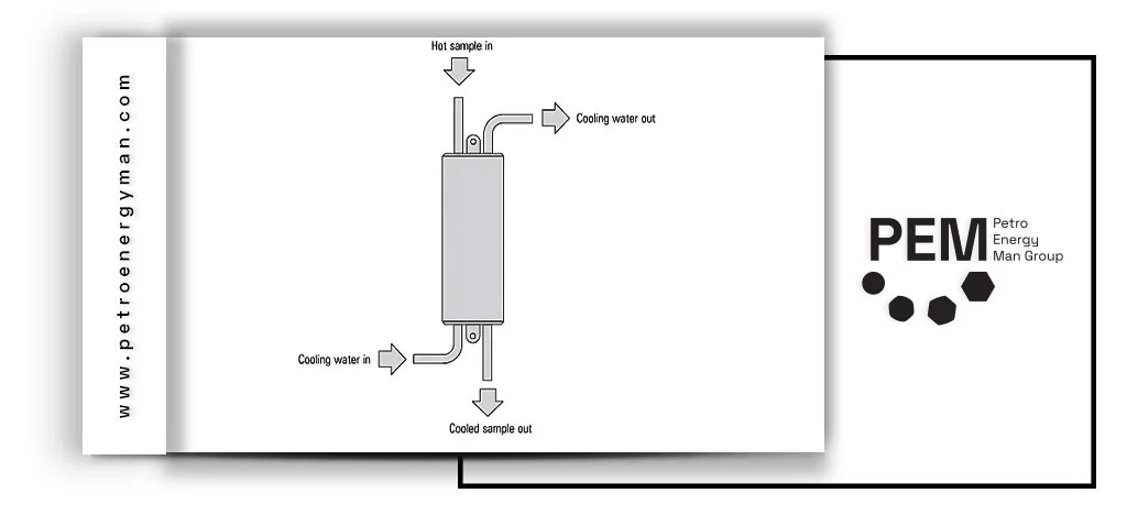
Sampling Connection
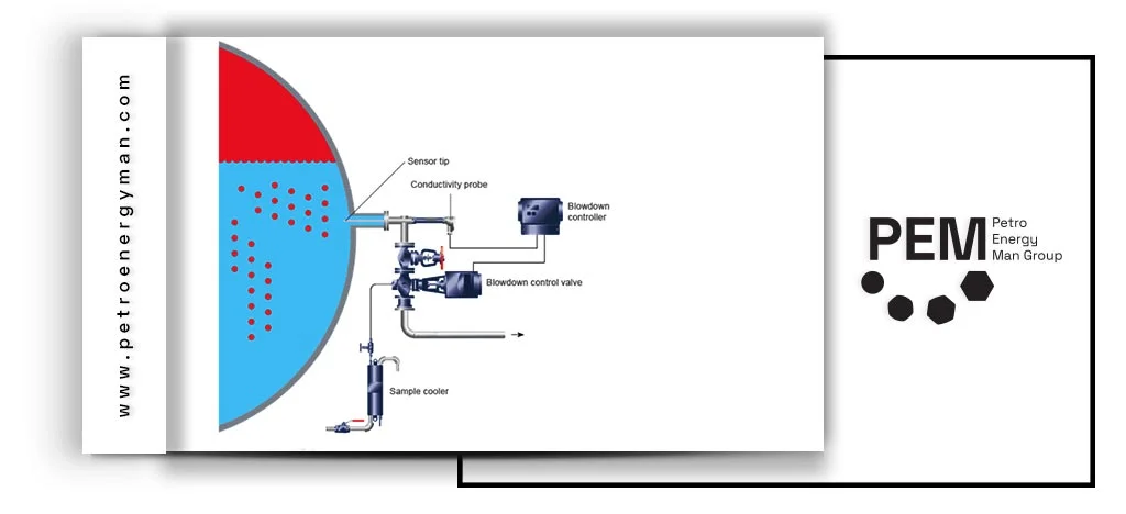
The boiler sampling connection typically consists of a control valve and a cooler, allowing the collection of feedwater samples for analysis at any time. The sample cooler is used to increase safety, prevent burns, and maintain the accuracy of test results. These devices prevent sudden evaporation and loss of volatile substances.
To ensure accurate testing and compliance with sampling standards, it is recommended to use stainless steel piping and carefully control the sample’s temperature and flow rate. These practices ensure that the collected samples accurately represent the boiler feedwater quality and provide reliable chemical analysis results.
Low-Level Alarm
Water Tube Boiler Accessories include the low-level alarm, a device that activates an audible warning when the water level in the steam drum drops below a set threshold. This alarm is a critical safety feature for the boiler, preventing continued fuel combustion when the water level is too low. Many systems also include an extremely low-level alarm that can shut down the burner to prevent overheating.

Soot Blowers
Soot blowers are designed to remove soot and combustion residues from boiler tube surfaces, typically using steam or compressed air. Regular cleaning of ash deposits from heat transfer surfaces is essential for maintaining boiler thermal efficiency and controlling flue gas temperatures within the design range.
Soot blowers can be designed as fully retractable, semi-retractable, or wall-mounted on the boiler, allowing cleaning operations without a full boiler shutdown and extending the service life of thermal equipment.
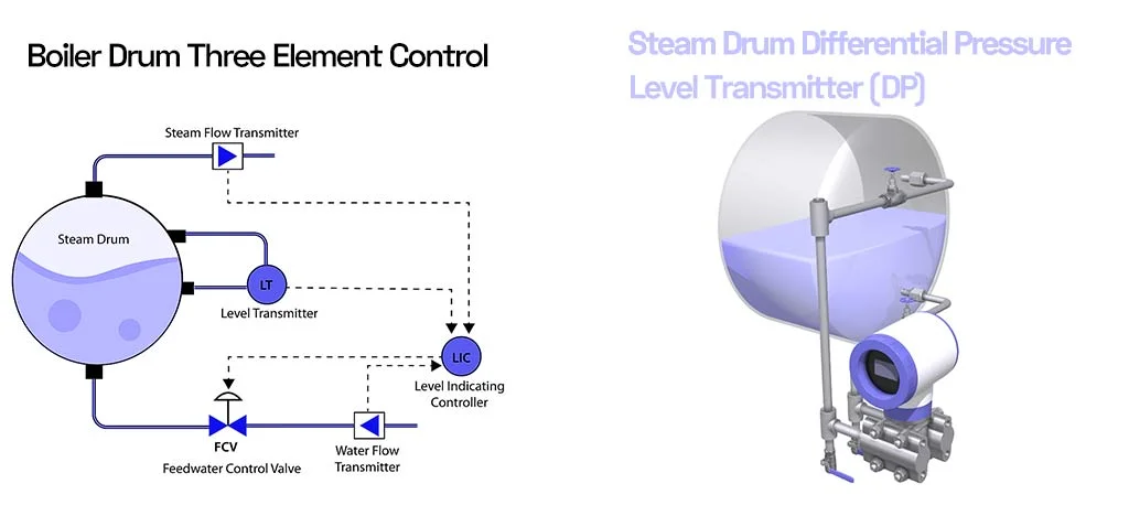
Automatic Feed Water Regulator
Boiler mountings include the automatic feed water regulator, a device that automatically adjusts the incoming water flow to the steam drum to maintain a constant and safe water level, even when the boiler load fluctuates. This device is usually installed on the feed line, before the main feed check valve, and automatically controls the water flow to ensure the desired water level is maintained in the steam drum.
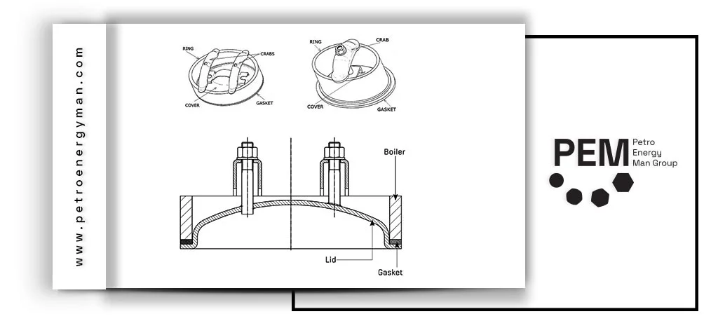
Manhole
Manholes are large openings in the water drum and steam drum that allow personnel to enter for inspection, maintenance, or internal cleaning of the boiler. In water tube boilers, these manholes are provided on all drums to ensure safe access to the interior for maintenance and inspection operations.
Manholes are typically designed in an oval shape, making it easier to install and remove the cover with less stress on the drum. This design ensures safe entry and exit for personnel while preserving the structural integrity of the boiler during opening and closing operations.
TDS Sensor and Probe
Water Tube Boiler Mountings include TDS (Total Dissolved Solids) sensors and probes, which are used for continuous monitoring of the dissolved solids concentration in boiler water. These devices measure the electrical conductivity of the boiler water to indicate the TDS level, enabling continuous water quality control.
If the TDS level exceeds the permissible limit, audible and visual alarms are activated, and by performing manual blowdown and adding fresh feedwater, the dissolved solids concentration is reduced, optimizing boiler water conditions.
To ensure accuracy and proper performance, regular inspection of TDS probes for physical damage, scaling, and clogging is essential. These inspections guarantee that the sensors consistently provide precise and reliable information about the boiler water quality.
Conclusion
This text provides a comprehensive overview of essential Water Tube Boiler Mountings, each playing a vital role in maintaining the stability and performance of the steam system. These components include main and auxiliary steam stop valves, safety valves, automatic feed water regulators, pressure gauges, steam drum level gauge glasses, blowdown and scum blowdown valves, air release valves, soot blowers, manholes, and TDS sensors.
All of these devices are designed to ensure safety, optimize efficiency, control water and steam levels, and enhance system reliability, playing a key role in the continuous and safe operation of industrial boilers.
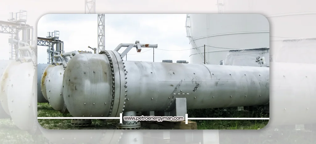
The shell and tube heat exchanger is one of the essential pieces of equipment in many large industries, used for heat transfer between two fluids. This type of exchanger has widespread applications in chemical industries, including crude oil distillation units. This comprehensive text provides an in-depth examination of these types of exchangers, offering complete information about their operation, components, types, applications, and testing methods. Join us to learn about the operation of these vital devices, their key components such as the shell, tubes, and baffles, as well as their diverse designs based on industrial standards and specific needs. This content serves as a comprehensive guide to better understand this complex technology and its broad applications across various industries.
What is a Shell and Tube Heat Exchanger?
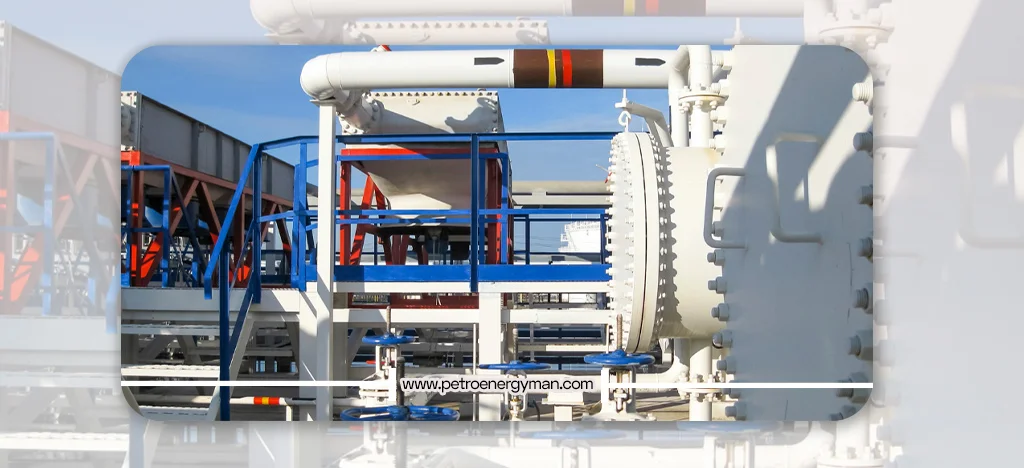
A Shell-and-Tube heat exchanger is a device used to transfer heat between two different fluids, usually liquids or gases. This exchanger is one of the most common and widely used types of heat exchangers in various industries. Its name comes from its basic structure, which consists of a large cylindrical vessel called the shell and a number of tubes inside it. This equipment is extensively used in many critical industries such as oil refineries, petrochemical plants, power plants, chemical industries, and other manufacturing processes.
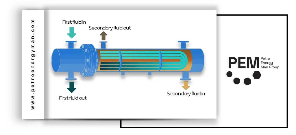
The general heat transfer mechanism in these exchangers is such that two fluids exchange heat with each other without direct mass contact. The fluid requiring heating or cooling flows through the tubes, while the other fluid flows outside the tubes, within the shell. This heat exchange occurs through the metallic tube walls, causing one fluid to heat up and the other to cool down. Ideally, without considering energy loss, the amount of heat lost by the hot fluid equals the amount of heat gained by the cold fluid.
The Shell-and-Tube heat exchanger is one of the most common types of heat exchangers, typically used in oil refineries and large process plants. This type of exchanger consists of a pressure vessel (shell) and a set of closely packed parallel tubes (tube bundle).
Operating Principles of Shell and Tube Heat Exchangers
Tube-and-Shell Heat Exchanger operate based on the concept of flow and thermal contact between two fluids. They transfer heat indirectly between a hot fluid and a cold fluid without the fluids mixing.
How Do Shell and Tube Heat Exchangers Work?
The tube and shell heat exchanger is one of the most widely used industrial pieces of equipment for heat transfer between two immiscible fluids. This exchanger consists of two main parts: the Shell, which is a cylindrical chamber, and the Tube Bundle, which is placed inside this shell. In this system, one fluid flows through the tubes, and the other fluid flows through the space between the tubes and the shell wall. The main objective is to transfer heat from one fluid to the other without them mixing. In other words, heat exchange occurs indirectly.
Fluid Flow Path: One fluid (e.g., the hot fluid) enters the tubes through the inlet nozzle and, after passing through the length of the tubes, exits from the other end. The second fluid (e.g., the cold fluid) enters the shell through another inlet nozzle and flows around the tubes. In this case, the heat from the hot fluid is transferred through the tube walls to the cold fluid without the two fluids mixing.
Flow Arrangement Design: In shell and tube heat exchangers, the movement of fluids can be designed in various configurations:
- Parallel Flow: Both fluids enter from the same side and exit to the same side.
- Counter Flow: Fluids enter from opposite ends and move towards each other. This arrangement usually has higher thermal efficiency.
- Cross Flow: The flow path of one fluid is perpendicular to the flow path of the other fluid.
Design of Shell and Tube Heat Exchangers
The design of Tube-and-Shell Heat Exchanger is one of the specialized processes in mechanical engineering and process industries. The primary goal in this process is to achieve the highest heat transfer rate with the lowest pressure drop and construction/operating costs. This design requires precise selection of geometric structure, suitable raw materials, and the use of advanced software for analyzing and optimizing exchanger performance.
Stages of Shell And Tube Heat Exchanger Design
Tube-and-Shell Heat Exchanger design is a complex process requiring significant knowledge and experience, and various factors must be considered. The general design stages are as follows:
Determining Requirements and Operating Conditions
The first step in heat exchanger design is defining the user’s needs and project specifications. These needs include the type of fluids used, required thermal capacity, fluid temperature difference (inlet/outlet), operating pressure, and cost considerations. The physical and chemical properties of the fluids, such as density, viscosity, and heat capacity, must also be specified at this stage.
Selecting the Exchanger Type
After determining the requirements, the appropriate type of heat exchanger is selected. Heat exchangers come in various types, including shell and tube, plate heat exchangers, double-pipe heat exchangers, and spiral heat exchangers. Shell and tube heat exchangers are one of the most common types. The selection of the exchanger type and baffle configuration is based on operating conditions and project needs.
Calculating Size and Heat Transfer Surface Area
After selecting the exchanger type, the size of the heat exchanger is calculated. This calculation is based on the required heat transfer rate and the overall heat transfer coefficient. The size of the heat exchanger depends on thermal capacity, fluid temperature difference, and heat transfer coefficient. The heat transfer coefficient is influenced by factors such as tube thickness, material properties, and fluid flow conditions.
Material Selection
The material of the shell and tubes must be selected according to operating temperature, pressure, and fluid properties to be resistant to corrosion and erosion. The type of fluids used in the heat exchanger impacts its design.
Mechanical Design
The mechanical design of the heat exchanger is performed after calculating its size. Mechanical design includes determining the exchanger dimensions, tube type, number of tubes, and type of tube sheets and gaskets. This design must comply with standards and safety requirements.
Fluid Flow and Pressure Drop Analysis
Important points regarding the placement of hot and cold fluids and pressure drop must be considered in Tube-and-Shell Heat Exchanger design. The pressure drop in the exchanger must be within the allowable range to ensure system efficiency. Baffles play a crucial role in flow distribution and pressure drop reduction
Using Design Software
Lorem ipsum dolor sit amet, consectetur adipiscing elit. Ut elit tellus, luctus nec ullamcorper mattis, pulvinar dapibus leo.
Specialized software plays a significant role in designing and simulating shell and tube heat exchangers. This software helps engineers perform precise and optimized designs. Several powerful software packages exist for Tube-and-Shell Heat Exchanger design, detailed below:
- HTRI Xchanger Suite: One of the most powerful tools for designing and simulating heat exchangers. Developed by Heat Transfer Research, Inc. (HTRI), it provides a wide range of software solutions for heat transfer equipment.
- Capabilities: HTRI Xchanger Suite includes various modules, each used for designing, simulating, and rating specific types of heat exchangers.
- Xist: The main module forTube-and-Shell Heat Exchanger . It allows precise evaluation of thermal performance and pressure drop.
- Xace: Used for designing and rating air coolers and economizers.
- Xphe: Used for plate heat exchangers.
- Xfh: An advanced tool for detailed analysis of fired heaters.
- Xvib: Used for analyzing tube vibrations.
Applications: This software helps operating companies, engineering contractors, exchanger manufacturers, and related industries design, simulate, and optimize heat exchangers with high accuracy.
Measurement of Shell-and-Tube Heat Exchangers
Measuring this type of heat exchanger is a fundamental step in the design and performance evaluation of such systems.
Measurement and Evaluation Methods
The measurement and evaluation of shell-and-tube heat exchangers involve several analytical and experimental methods aimed at optimizing performance and efficiency.
Calculation of Heat Transfer Surface Area
Calculating the tube surface area in a shell-and-tube heat exchanger is essential for designing an efficient system. This area directly affects the heat transfer capacity of the exchanger. The determination of the heat transfer surface area should be based on the required heat duty and the desired capacity of the exchanger.
Thermal and Hydrodynamic Analysis
Extensive experimental and numerical studies have been conducted to investigate the thermal and hydrodynamic performance of shell-and-tube heat exchangers.
- Analytical and Experimental Methods: The heat transfer rate along the tube can be calculated using analytical and experimental techniques. For example, the tube-side heat transfer coefficient in a helical coil has been measured using the Wilson plot method. In addition, numerical studies have been carried out on the freezing and melting behavior of phase change materials in triple-tube heat exchangers using fins and nanoparticles.
- Modeling and Simulation: Thermal modeling of shell-and-tube heat exchangers is performed using the e-NTU method, and optimization is conducted with multi-objective genetic algorithms to enhance efficiency and reduce overall annual costs.
- Effect of Nanofluids: The use of nanofluids such as water–aluminum oxide and multi-walled carbon nanotube–water can significantly improve heat transfer rates. For instance, a water/alumina nanofluid can increase the heat transfer rate by up to 9%, while multi-walled carbon nanotubes in water can enhance the heat transfer coefficient by up to 75%.
Design and Selection Considerations
The selection and sizing of a heat exchanger require an understanding of the types of exchangers, available options, and the application environment. The main criteria for measurement and selection include:
- Exchanger performance: The function of the exchanger (e.g., condensation or boiling).
- Pressure and temperature limitations: Operating pressure (high/low) and the temperature range that may vary during the process.
- Fluid flow capacity: The exchanger’s ability to handle a certain volume of fluid.
- Required materials: Conditions such as sudden temperature changes or corrosive environments may require specific materials.
- Thermal fluid properties: If the fluid is prone to fouling, corrosion-resistant materials may be necessary.
- Space and layout constraints: Physical space limitations and system arrangement can influence the choice of exchanger model.
- Maintenance requirements: Ease of cleaning, repair, and inspection can also be an important factor.
Measurement Tools
Various instruments are used to measure and monitor the performance of heat exchangers, including:
- Temperature sensors: To monitor temperatures at different points in the exchanger.
- Rotameters: For measuring and adjusting the flow rate of hot and cold fluids.
- Control panels and monitoring systems: Including displays and other instrumentation devices for controlling and supervising performance.
- Safety equipment: Appropriate safety tools, such as goggles and gloves, are essential when working with heat exchangers.
These tools, together with thermodynamic calculations and fluid mechanics analysis, contribute to optimal selection and accurate measurement of shell-and-tube heat exchangers.
Price of Shell and Tube Heat Exchangers
The price of shell and tube heat exchangers depends on several factors, including:
- Material of Construction: The type of material used for the shell, tubes, tube sheets, and baffles (e.g., carbon steel, stainless steel, copper, titanium, special alloys) directly affects the price. Materials resistant to corrosion or high temperatures are more expensive.
- Size and Capacity: Larger exchangers with higher heat transfer capacity have higher costs.
- Operating Pressure and Temperature: Design for high pressures or very high temperatures requires thicker materials and more complex manufacturing processes, increasing the price.
- Type and Configuration: Specific types like U-tube exchangers, floating head types, or special baffle designs can impact the final price.
- Standards and Certifications: Compliance with international standards like TEMA (Tubular Exchanger Manufacturers Association) or ASME (American Society of Mechanical Engineers) and the need for specific certifications can add to the cost.
- Ancillary Equipment: The presence of equipment like valves, instrumentation, insulation, and supports also affects the final price.
Geometric Terms in Shell and Tube Exchangers
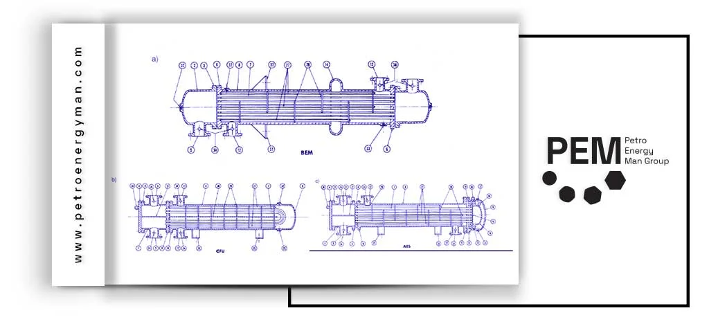
Components of Shell And Tube Heat Exchanger
Tube-and-Shell Heat Exchangers consist of numerous components, each playing a vital role in the system’s performance and integrity. Understanding these components and their materials is essential for optimal design, construction, and maintenance.
Shell
This is the large pressure vessel that houses the tube bundle. Its function is to direct the flow of the fluid outside the tubes and ensure efficient heat transfer.
Tubes
Tubes are the primary heat transfer elements through which the primary fluid flows. They are typically made of high-quality stainless steel or copper, known for excellent thermal conductivity and durability. Seamless tubes are produced via extrusion, while welded tubes are made by rolling a strip into a cylinder and welding the seam; welded tubes are usually more cost-effective. Common tube diameters are 5/8, 3/4, and 1 inch. Tubes with smaller diameters are more difficult to clean mechanically, while larger tubes are used to facilitate cleaning or reduce pressure drop. Tube wall thickness typically ranges between 12 to 16 BWG (0.109 to 0.065 inches). Thinner-walled tubes (18 to 20 BWG) are used when expensive materials like titanium are employed.
Tube Sheets
These are thick metal plates with precisely drilled holes for securing the tubes. Tube sheets are critical for maintaining the structural integrity of the heat exchanger and preventing fluid mixing. They must resist corrosive attack from both fluids and be electrochemically compatible with the tube and tube-side materials. The “tube pitch” is the distance between tube hole centers, typically 1.25 times the outer tube diameter. Triangular pitch is used for higher heat transfer and compactness, while square pitch is used for easier mechanical cleaning. Forged tube sheets are produced using compressive forces, resulting in higher strength and durability compared to casting or machining methods, making them ideal for high-stress applications.
Baffles
Baffles are metal plates strategically placed inside the shell to direct the fluid flow across the tubes. They improve heat transfer efficiency by increasing fluid velocity and ensuring multiple passes over the tubes.
Tie Rods and Tie Rod Nuts
Tie rods hold the baffles in place and maintain their spacing within the shell. Nuts secure these rods, ensuring the stability and alignment of the entire assembly.
Spacer Tubes
These tubes maintain the proper distance between baffles and ensure uniform tube spacing within the bundle. They prevent tube contact, which could cause damage and reduce efficiency.
Body Flanges and ANSI Flanges
These parts connect different sections of the heat exchanger, enabling easy assembly, disassembly, and maintenance. Designed for tight sealing and strong connections.
Studs and Nuts
Used to fasten flanges and ensure a strong seal, preventing leaks.
Applications of Shell and Tube Heat Exchangers in Industries
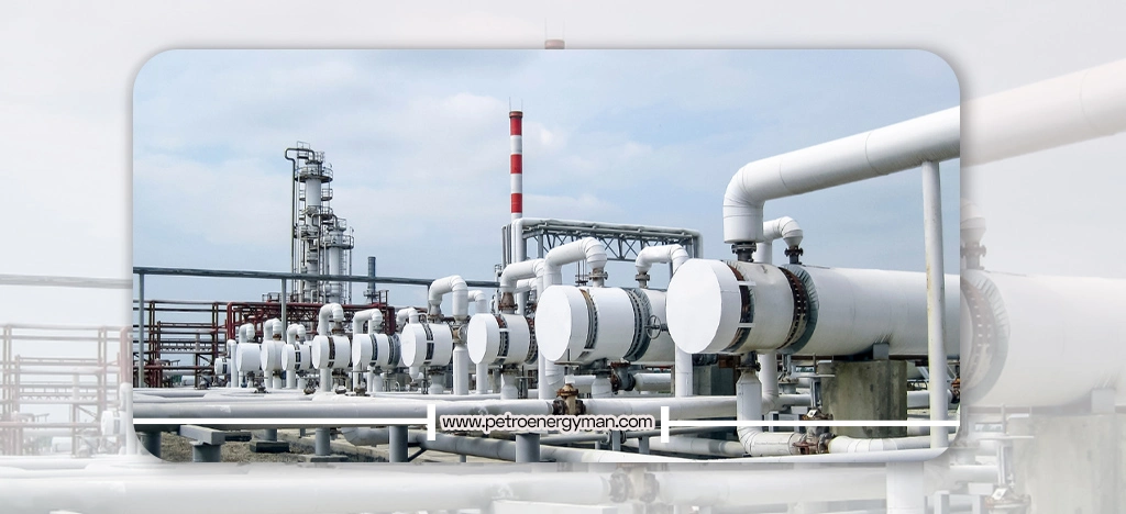
The high adaptability and reliability of shell and tube heat exchangers make them an integral part of a wide range of industries. Their widespread use across various sectors, from heavy and processing industries to sensitive areas like food and pharmaceuticals, demonstrates their robustness and unparalleled ability to adapt to different fluids, temperatures, and pressures. These features make them a fundamental technology, not just a specific solution, but a vital component in industrial infrastructure.
Oil, Gas, and Petrochemical Industries: These exchangers are used for heating or cooling chemicals, oils, and gases in processes like distillation, condensation, and chemical reactions. In refineries, they are used for crude oil distillation, preheating and cooling fluids, maintaining optimal temperatures in catalytic reactions, condensing vapors, and cooling towers. Due to their durability and high resistance to harsh temperature and pressure conditions, they are highly suitable for the demanding environments of this industry. They are also used in heat recovery processes during oil-water-gas separation.
Power Generation: In power plants, shell and tube heat exchangers serve as condensers, converting steam water into liquid water for return to boilers. They are critical for maintaining the temperature of turbine and generator cooling water systems, preventing overheating, and ensuring uninterrupted power generation. They are also used for feedwater preheating, gearbox oil cooling, and heat recovery from exhaust gases to increase overall efficiency.
Food and Beverage Industries: Used for pasteurizing, sterilizing, and cooling liquids like juices, dairy products, and sauces. Maintaining precise temperatures is vital for product quality and safety. Stainless steel is a common material choice due to its corrosion resistance and ease of cleaning.
Pharmaceutical Industry: Tube-and-Shell Heat Exchangers are used for precise temperature control in processes such as crystallization, distillation, and sterilization of pharmaceutical materials.
Shell and Tube Heat Exchanger Pressure Testing Methods
Pressure testing is critical for confirming the safety and integrity of pressure vessels. The primary goal is to detect any leaks or weaknesses in the coils and connections. Failure to comply with protocols can lead to equipment damage or catastrophic failures.
Hydrostatic Testing
Hydrostatic testing is one
of the most common and safest methods for pressure testing shell and tube heat
exchangers. In this process, the equipment is filled with clean water and
subjected to pressure exceeding the maximum allowable operating pressure to
ensure there are no leaks, structural defects, or mechanical weaknesses. The
applied pressure is typically between 1.3 to 1.5 times the design pressure, but
according to ASME requirements, it may be up to 4 times the design pressure in
some conditions.
This test is performed in several main stages: First, the
exchanger is completely isolated, and all valves are closed. Then, vents are
installed to remove trapped air bubbles, and the system is completely filled
with water. Next, the water pressure is gradually increased to the specified
limit. This pressure is maintained for a specified duration to allow sufficient
time for inspection. During pressure application, the operator visually
inspects all welds, connections, and flanges to ensure there are no leaks or
defects.
After completing the test, the pressure is slowly reduced, and the
water is drained. The exchanger is then thoroughly dried to prevent internal
corrosion. Important considerations for this test include maintaining suitable
water and equipment temperatures. The water temperature should be at least 60°F
(15°C), and the metal temperature should not be below the minimum design
temperature to prevent thermal cracking. Compared to gas methods, hydrostatic
testing is safer because the stored energy in liquids is significantly less
than in gases, thus greatly reducing potential hazards in case of leaks or
failures.
Pneumatic Testing
Pneumatic testing is a common method for assessing the strength and sealing of heat exchangers and other pressure equipment, especially when water cannot be used or is undesirable due to reasons like preventing moisture ingress or difficulty in complete drainage. In this method, compressed gases such as air, nitrogen, or other inert gases are used instead of water. In the pneumatic testing process, gas is introduced into the system in a controlled and gradual manner to increase the pressure uniformly.
The test pressure is usually set at 1.1 times the maximum working pressure. If there is a leak, the sound of escaping gas or visible signs are usually quickly detectable. However, unlike hydrostatic testing, pneumatic testing carries a higher risk because compressed gases store significant energy and can cause serious damage or even life-threatening hazards in case of sudden rupture or leakage. Therefore, strict adherence to safety precautions is essential.
The test must be performed in a controlled environment following stringent safety protocols. To reduce risk, operators often use cameras or remote monitoring equipment to observe the test status without physical proximity. Also, the number of people present on-site should be minimized. Overall, pneumatic testing is an effective and precise solution under specific conditions but requires careful management and completely safe execution to ensure reliable equipment performance without creating hazards.
Precision Leak Testing (Leak Test)
Precision leak testing is one of the most advanced and sensitive methods for assessing the integrity of pressure equipment like heat exchangers. This test is particularly applicable in industries where even the smallest leak can have serious consequences, including pharmaceuticals, nuclear, high vacuum, and other applications requiring complete sealing.
Among various methods, Helium Mass Spectrometry is the most accurate and widely used technique. In this method, helium gas is used as the tracer material because its small atoms can pass through the tiniest cracks and pores. After injecting the gas inside or around the equipment, the spectrometer measures the leak rate with very high precision, in scales of ppm (parts per million) or ppb (parts per billion). This test can detect microscopic leaks that are undetectable by traditional methods and is therefore used as a standard tool in sensitive industries.
Early and precise detection of such leaks can prevent safety, environmental, or operational hazards and reduce costs associated with production stoppages or emergency repairs.
Scanning and Detection Tools
Scanning and detection tools play an important role in monitoring the internal condition of heat exchangers and other pressure equipment. These tools are used to identify damage such as corrosion, cracks, erosion, pitting, and internal cavities and serve as a vital complement to pressure tests, enabling non-destructive and precise evaluation.
Types of Shell and Tube Heat Exchangers
Tube-and-Shell Heat Exchanger are classified based on various criteria such as design standard, fluid flow mechanism, and material of construction, each with its own advantages and specific applications.
Based on TEMA Standard
According to the TEMA (Tubular Exchanger Manufacturers Association) standard, exchangers are classified based on front/rear head series configuration and shell type. This standard includes different classes, each with specific applications:
- Class B: Tube-and-Shell Heat Exchanger used in chemical processes.
- Class C: Exchangers for general service in various industries.
- Class R: Tube-and-Shell Heat Exchanger designed and used for petrochemical industries and large-scale processes.
Based on Fluid Flow Mechanism
- Shell and tube heat exchangers are also divided into different categories based on how fluids flow within the equipment:
- Parallel Flow: In this type, both fluids move in the same direction, causing the temperature difference between them to gradually decrease along the exchanger.
- Counter Flow: In this case, fluids flow in opposite directions, increasing heat transfer efficiency, commonly used in many applications.
- Cross Flow: In this type, fluids flow perpendicular to each other, typically used in exchangers with specific designs.
- Combined Flow: This involves a combination of the above mechanisms, employed to improve heat transfer and adapt to specific design conditions.
Based on Material of Construction
The selection of the material for shell and tube heat exchangers is based on fluid type, temperature, pressure, and corrosion resistance. This diversity in materials allows exchangers to perform well in very challenging environments and various operating conditions.
Copper: Known for its very high thermal conductivity, commonly used in general applications and situations requiring rapid heat transfer.
Titanium: Due to excellent corrosion resistance, especially in environments containing chlorides and acids, suitable for specific and expensive applications.
Stainless Steel: This material offers good corrosion resistance, and its ease of cleaning makes it a popular choice in food and pharmaceutical industries.
Nickel Alloys: These alloys are used for highly corrosive environments and extreme temperature conditions due to exceptional corrosion resistance and high strength at elevated temperatures.
Carbon Steel: This type of steel is widely used in various industries due to its cost-effectiveness, acceptable corrosion resistance, and suitable thermal conductivity.
Special Materials: Such as graphite, ceramic, composite, and plastic, typically used in special applications requiring specific chemical or thermal resistance.
Based on Operating Pressure and Overall Structure
Exchangers can be designed to withstand different operating
pressures and are categorized by overall structure into the following types:
Double Pipe Exchangers: These are the simplest type, consisting of
a smaller tube inside a larger tube. These exchangers have less heat transfer
surface area and are often used in low-capacity applications or for gaseous
fluids at high pressure.
Air-Cooled Exchangers: These exchangers are equipped with fans and
are used to cool fluids without using liquids.
Plate Heat Exchangers: In this type, multiple plates are used for
heat transfer instead of tubes, offering a more compact structure and higher
efficiency than tubular exchangers.
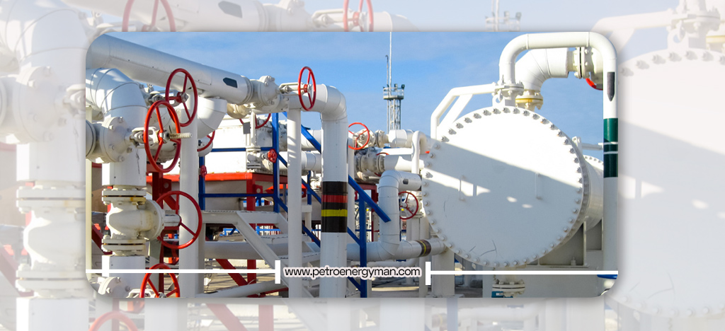
Manufacturers of Shell and Tube Heat Exchangers
Manufacturers of Tube-and-Shell Heat Exchangers operate worldwide
and in Iran. These companies specialize in the design, manufacture, and
installation of various types of heat exchangers for oil and gas,
petrochemical, power generation, food, pharmaceutical, and HVAC industries.
Among manufacturers, Petro Energy Man Holding, with an outstanding
record in designing and producing shell and tube heat exchangers, is recognized
as one of the reputable companies in this industry due to its specialized and
flexible approach. Relying on engineering knowledge and a precise understanding
of market needs, this company has played a significant role in key industries
of the country. Manufacturing high-quality equipment, compliance with
international standards, and providing full services from design to
commissioning are part of Petro Energy Man’s capabilities in providing
professional industrial solutions.
For specialized consultation, technical assessment of your
project’s needs, and ordering custom-built heat exchangers tailored to your
requirements, Petro Energy Man’s experts are ready to assist.
Contact Number: +98 21 5742 3000
Finding Shell And Tube Heat Exchanger Manufacturers Near Me
To find Tube-and-Shell Heat Exchanger manufacturers near you, you can use the following methods:
- Online Search: Using search engines with phrases such as “Tube-and-Shell Heat Exchanger manufacturer in [city or province]”.
- Industrial Associations: Visit the websites of relevant industrial associations (e.g., oil and gas, petrochemical) which may provide a list of manufacturers.
- Industrial Exhibitions: Attend specialized industrial exhibitions where manufacturers of this equipment are present.
- Consulting Specialists: Inquire with engineers, industrial consultants, or partner companies who may have experience working with local manufacturers.
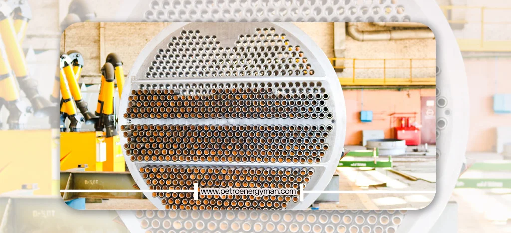
Conclusion
Shell and tube heat exchangers, due to their reliability, efficiency, and flexibility, are the backbone of many industrial processes. With technological advancements, the design and construction of these exchangers are moving towards increased energy efficiency, reduced size, use of more advanced materials, and greater resistance to corrosion and fouling. Additionally, the development of computer simulation and optimization methods has enabled the design of exchangers with higher performance and lower cost.
If you are looking to purchase, design, or consult about Tube-and-Shell Heat Exchangers, you can call +98 21 5742 3000 or contact Petro Energy Man consultants via Instagram ID @petroenergyman.
A heat exchanger is one of the most widely used industrial equipment, playing a key role in transferring heat between two fluids. In this article, we will introduce the types of heat exchangers, how they work, their advantages, and their applications in various industries. If you want a comprehensive understanding of this important and practical equipment, stay with us until the end.
What is a Heat Exchanger?
A heat exchanger is an engineered device designed to transfer heat between two or more fluids at different temperatures. These fluids can be liquids, gases, or a combination of both. The main purpose of this device is to increase or decrease the temperature of one fluid using another. This heat transfer usually occurs without direct contact between the fluids and is carried out through a conductive wall (such as the wall of a tube or plate). This feature greatly helps maintain the integrity of the fluids and prevents mixing.
For example, a car radiator transfers heat from the engine to the air, or swimming pool heat exchangers transfer boiler-heated water to pool water without direct contact. Boilers and chillers are other examples of heat exchangers commonly used in everyday life and industry.
In this video, you can watch the fabrication process of a heat exchanger (tube installation) in the oil and energy industry. These devices play a vital role in heat transfer and in optimizing industrial processes.
Comparison Table of Key Parameters of Heat Exchanger
| Description | Shell-and-tube | Plate-and-frame | Spiral-plate | Printed-circuit | Air-cooled |
|---|---|---|---|---|---|
| Efficiency | Moderate | High | High | High | Moderate |
| Footprint | High but not as high as air fin cooler | Moderate | Small | Small | Large |
| Range of applicability (temperature, pressure, and transients) | High | Moderate | Low | Low | Moderate |
| Suitability to be used in fouling service | Yes | No | No | No | No |
Applications of Heat Exchangers
Heat exchangers are vital tools in various industries and have wide-ranging applications
Oil, Gas, and Petrochemical Industry
This industry is one of the most critical consumers of heat exchangers. They are used for distillation of solvents and multi-component mixtures, cooling and heating of reactors and product storage tanks, and as hydrocarbon coolers (e.g., ethylene, propylene, benzene, ethane, propane, butane). They are also applied in water circuit cooling, heat recovery (such as benzene heat recovery), as condensers and evaporators, and for heating natural gas (before or after expansion). Other applications include heating fuels to reduce viscosity, producing hot water for boilers, heating crude oil and sour gas, preheating naphtha in the ethylene process, and cooling sodium hydroxide. Without heat exchangers, core operations in petrochemical, oil, and gas plants would not be possible. Companies like PetroenergyMan
are among the leading manufacturers and suppliers of industrial heat exchangers, providing reliable solutions for these critical processes.
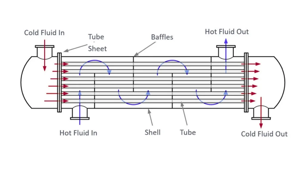
HVAC (Heating, Ventilation, and Air Conditioning) and Refrigeration
Heat exchangers are used in central heating and air conditioning systems in buildings (residential and commercial). Coils, a type of heat exchanger, are used in fan coil units for heating or cooling air. Over the last decade, heat exchangers have become increasingly common in chillers due to their higher efficiency. Air-cooled heat exchangers (condensers and evaporators) are also widely used in the refrigeration industry. Heating of swimming pools (domestic, chlorinated, large baths) is also achieved through heat exchangers, where boiler-heated water transfers heat to the pool water.
Power Plants
Heat exchangers are used in power plants to convert thermal energy into electricity, cool components, and recover waste heat. In nuclear power plants, they safely and efficiently separate the radioactive reactor circuit from the power generation circuit, preventing radioactive leakage into the environment. The Bushehr Nuclear Power Plant in Iran, for instance, uses shell-and-tube heat exchangers.
In solar power plants, they are necessary for transferring and isolating heat to the working fluid, enabling efficient high-pressure steam production. Wind power plants use heat exchangers to cool generators, transformers, electrical equipment, gearboxes, and bearings, ensuring efficiency and preventing damage
In steam power plants, they play a key role in producing steam for turbine rotation, cooling condensers, and heating boiler feedwater. Combined-cycle and gas power plants use them for steam generation, cooling components (such as gas turbines, generators, and air compressors), recovering waste heat from flue gases, and cooling intake air for turbines. The selection of heat exchanger type depends on factors such as application, available space, and fluid properties.
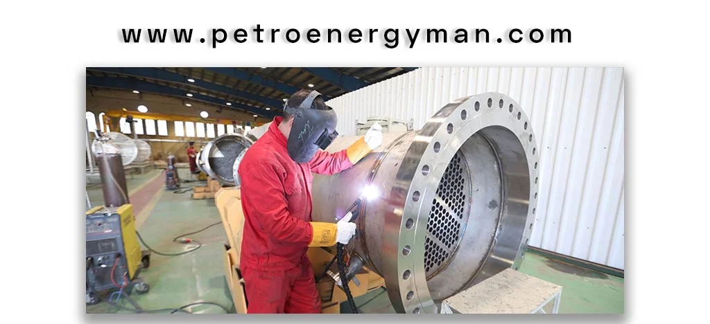
Food and Pharmaceutical Industries
In the pharmaceutical industry, heat exchangers are essential for heating, cooling, or maintaining the temperature of materials during the drug production cycle, since over 90% of processes require temperature control. Water is the primary medium used for thermal regulation. Applications include pure steam distillation, ethanol and methanol production, disinfectant solutions, pasteurization, active ingredient extraction, and distilled water production. Plate heat exchangers, due to their specific design, are widely used in this sector.
In the food industry, heat exchangers play a critical role in improving product quality and eliminating microbes. Applications include pasteurization of various food products such as milk, tomato paste, cream, juice, and cheese. Beyond pasteurization, they are also used in drying, fermentation, pre-processing, evaporation, sterilization, yeast production, cooking, crystallization, freezing, and mixing. Plate heat exchangers made of stainless steel (SS304) are extensively used in this industry.
Chemical Industry
Heat exchangers in the chemical industry are used for cooling and heating process environments, phase changes (such as converting vapor to liquid or vice versa), and controlling temperature and pressure in chemical reactions. They play a crucial role in improving efficiency and heat transfer in processes such as distillation, condensation, and chemical reactions.
Automotive Industry
In the automotive industry, heat exchangers are used in the production of various parts and for cooling electronic components such as processors and transistors. They are also applied in engine oil coolers, power steering, and battery cooling systems in advanced vehicles, as well as in radiators. Electric vehicles, due to their higher thermal management requirements, need heat exchangers with much greater efficiency compared to gasoline-powered cars
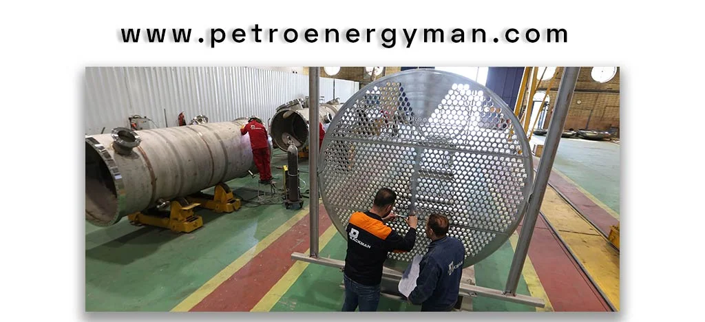
Metallurgy and Steel Industry
In metallurgy and steel
industries, heat exchangers are used for product shaping, cooling lubricants
such as oils, and controlling the temperature of various fluids. Other
important applications include cooling casting equipment, furnaces, and molds,
as well as in the production of compressors, pickling lines, hot and cold
rolling, continuous casting, and cooling galvanized steel products. Continuous
temperature regulation and cooling in these industries ensure the high quality
of output products.
Wastewater Treatment and Desalination
Heat exchangers are used for heating and cooling water in water treatment cycles and for producing fresh water from seawater. In addition, pool heat exchangers are also applied in wastewater heat recovery processes.
Marine Industry
Heat exchangers are essential equipment for marine systems, cargo ships, and commercial vessels. Their applications include oil coolers, water coolers in closed-loop systems, fuel heating systems, desalination units, and cooling of engines, generators, and other onboard equipment. Due to the corrosive marine environment, materials such as stainless steel, nickel-chrome alloys, and titanium (the most effective option) are commonly used in their construction.
Functions of Heat Exchangers
The functions of heat exchangers go beyond merely transferring heat and encompass strategic objectives in industrial processes:
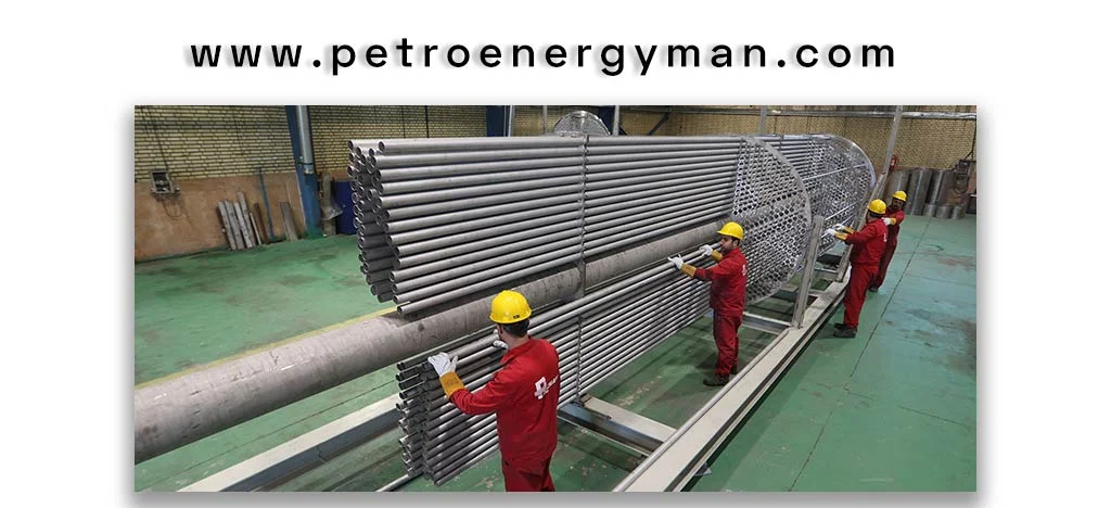
Heat Transfer
The primary and fundamental purpose of heat exchangers is to transfer heat between two or more fluids to achieve or maintain the desired temperature. This process can involve heating or cooling of fluids and directly affects the quality and efficiency of the final product
Efficiency Improvement
By optimizing the heat exchange cycle, heat exchangers help increase the efficiency and thermal output of systems. This efficiency depends on factors such as surface area, construction materials, hydraulic design, and cleanliness of the exchanger. For example, in HVAC systems, heat exchangers improve device performance, reducing the energy required to achieve optimal temperature and humidity conditions.
Energy Optimization and Heat Recovery
One of the most important functions of heat exchangers is recovering heat from outgoing fluids (such as exhaust air from buildings or flue gases in power plants). This reduces the need for heating or cooling of incoming fluids, leading to significant energy savings, cost reduction, increased system efficiency, and decreased thermal load on equipment. Moreover, heat recovery contributes to reducing greenhouse gas emissions and improving energy resource management, highlighting the environmental significance of heat exchangers.
Equipment Protection and Temperature Control
Heat exchangers maintain optimal fluid and component temperatures, preventing damage to sensitive equipment (such as processors, transistors, and batteries in vehicles or turbines and generators in power plants). Precise temperature control is also critical in sensitive operations like pharmaceutical production and maintaining product quality in the food industry. This temperature management ensures operational stability and safety.
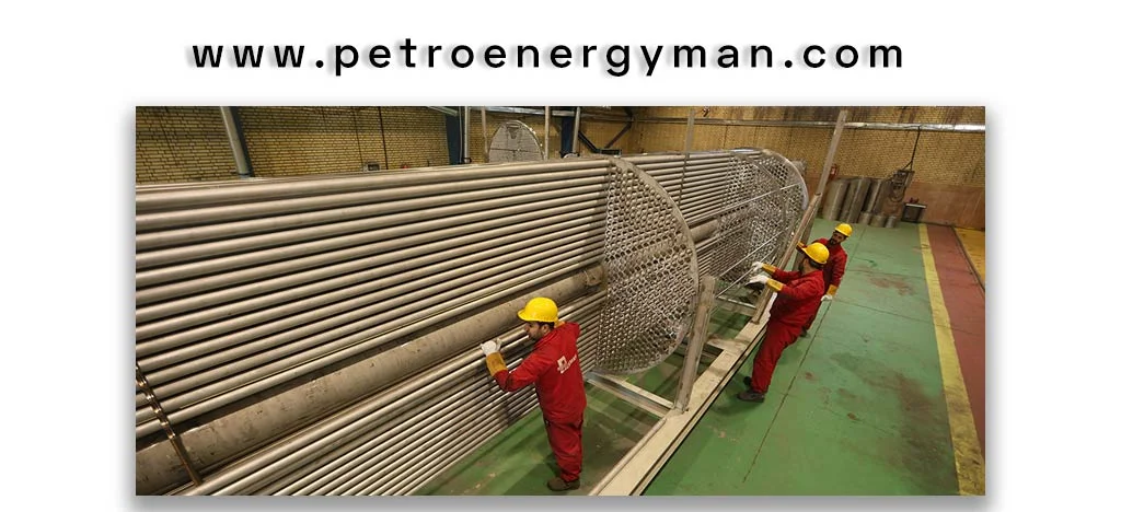
Contaminant Separation and Product Purification
In certain industrial applications, such as refineries and petrochemical complexes, heat exchangers play a vital role in distillation, purification, evaporation, condensation, mixing, and separation of materials. They assist in separating various products (e.g., gasoline, diesel) by heating crude oil before entering the distillation column and cooling the output products. Heat exchangers are also used in treatment units (like hydro-treating) and condensation processes, improving the quality and purity of final products.
The role of heat exchanger design is crucial in achieving these functions effectively.While heat transfer remains the primary function of heat exchangers, other roles—such as enhancing efficiency, optimizing energy use, and protecting equipment—demonstrate that they are not isolated components but essential elements within a larger system. They indirectly influence operational economics (cost reduction), environmental sustainability (emission reduction), and process safety (equipment protection).
This means that the value of heat exchangers lies in their ability to create positive ripple effects throughout the entire chain. Repeated emphasis on heat recovery and energy reduction, and their connection to reducing greenhouse gas emissions and dependency on fossil fuels, underscores a significant trend. Heat exchangers serve as key tools for achieving sustainability goals across various industries. This goes beyond a mere operational advantage; it is a strategic necessity in today’s era, where industries aim to reduce carbon footprints and increase resource efficiency. Consequently, the demand for higher-efficiency heat exchangers with energy recovery capabilities continues to grow.
Classification of Heat Exchangers
Heat exchangers are classified based on several key criteria, helping engineers choose and design the most suitable type for specific applications.
| Classification | Type | Description |
|---|---|---|
| Fluid Flow | Parallel Flow | Fluids move in same direction |
| Counter Flow | Fluids move in opposite directions | |
| Cross Flow | Perpendicular flow | |
| Combined Flow | Mix of above flows | |
| Construction | Recuperator | Continuous heat transfer through wall |
| Direct / Indirect | With or without direct contact | |
| Element Type | Shell & Tube | Cylindrical shell with tube bundle |
| Double Pipe | Small tube inside large tube |
Based on Fluid Flow Arrangement
- Parallel Flow (Cocurrent Flow) Exchanger: In this type, the shell-side fluid and tube-side fluid enter the heat exchanger from the same side and move in the same direction toward the opposite end.
- Counter Flow (Countercurrent Flow) Exchanger: The shell-side and tube-side fluids enter the system from opposite ends and exit from the other side. This is the most common and efficient flow mechanism in heat exchangers.
- Cross Flow Exchanger: The direction of the shell-side fluid is at a 90-degree angle to the tube-side fluid. In this system, one of the fluids may undergo a phase change.
- Hybrid/Combined Exchanger: In some cases, depending on the design and application, a combination of the above flow arrangements may be used.
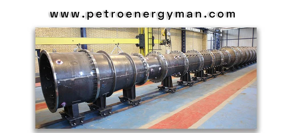
Based on Construction Method
- Recuperator Exchanger: These exchangers continuously transfer heat between two fluids through a fixed wall.
- Direct and Indirect Heat Exchangers: Direct exchangers transfer heat through direct contact between fluids (e.g., wet cooling towers), whereas indirect exchangers separate the fluids with a barrier wall.
Based on Construction Elements
· Shell and Tube: The most common type, consisting of a cylindrical shell and a bundle of parallel tubes. One fluid flows inside the tubes while the other flows through the shell. It includes baffles to create turbulence and tube sheets to hold and seal the tubes. This type can withstand high pressures and temperatures. Subtypes include U-tube designs and TEMA standard classifications (B, C, R).
· Double Pipe (Tube-in-Tube): The simplest type, consisting of a smaller tube inside a larger one. It has a limited heat transfer area and is suitable for small capacities and high-pressure applications.
Considerations for Sizing Heat Exchangers
Determining the appropriate size and capacity of a heat exchanger is crucial for optimal and cost-effective system performance. This process is complex and depends on multiple factors:
| Factor | Description |
|---|---|
| Fluid Properties | Type, viscosity, thermal conductivity, density, specific heat; corrosion or scaling may require special design. |
| Temperature & Pressure | Inlet/outlet temps and pressures; high values may need specialized exchangers (e.g., long spiral tubes). |
| Flow Rate | Fluid speed affects heat transfer and pressure drop. |
| Phase Change | Evaporation or condensation impacts design and size. |
| Maintenance & Cleaning | Ease of inspection and cleaning, important for scaling-prone fluids. |
| Cost | Includes initial purchase, operating energy, and future expansion potential. |
| Material Compatibility | Seals and materials must resist corrosion and be compatible with fluids. |
Factors Affecting Size Selection
· Fluid Properties:
The type of fluid, viscosity, thermal conductivity, density, and heat capacity directly impact the heat exchanger’s capacity. Fluids prone to fouling require corrosion-resistant materials or specialized designs.
· Temperature and Pressure Range:
The inlet and outlet temperatures and pressures of the fluids, as well as the exchanger’s ability to withstand them, are key factors. For extremely high temperatures (e.g., 600 °C) or pressures (e.g., 350 bar), specialized designs such as long coiled tube exchangers are required.
· Flow Rate:
The fluid’s flow rate directly affects heat transfer and pressure drop; higher flow rates increase both heat transfer and pressure loss.
· Phase Change of Fluids:
Whether the fluid undergoes a phase change (e.g., evaporation or condensation) strongly influences the design and size of the heat exchanger.
· Spatial Considerations (Footprint):
Space limitations and layout constraints may affect the choice of suitable heat exchanger models.
· Maintenance and Cleaning Requirements:
Ease of cleaning and inspection, particularly for fluids prone to fouling, is an important factor in design selection.
· Overall Cost:
Includes initial purchase cost, operational energy consumption, and future system expansion possibilities.
· Material Compatibility:
Gaskets and construction materials must be compatible with the fluids used and resistant to corrosion.
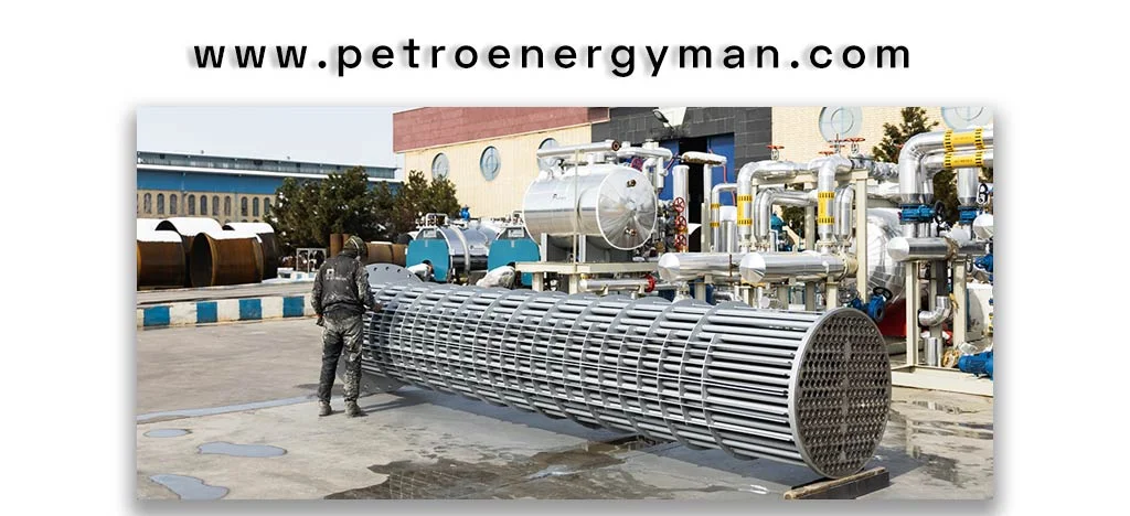
Components and Functioning of Heat Exchangers
Heat exchangers, especially the shell-and-tube type which is among the most common, consist of several components, each playing a specific role in the heat transfer process. These components work together in harmony to achieve efficient thermal exchange
Components of Heat Exchangers
The shell, tubes, baffles, tube sheets, nozzles, and so on are parts of heat exchangers, each of which is explained separately.
Shell
The shell is a large cylindrical enclosure that surrounds the tubes. The shell-side fluid flows inside this chamber and comes into contact with the outer surfaces of the tubes.
Tubes
Tubes are a set of parallel pipes placed inside the shell. They can be either straight or U-shaped, and their diameter and thickness vary depending on the application. The tube-side fluid passes through these tubes. The tube walls provide the main surface for heat transfer between the two fluids.
Baffles
Baffles are plate-like obstacles placed along the shell-side flow path. They have characteristics such as baffle cut and baffle spacing. The main functions of baffles include:
- Directing the flow of the shell-side fluid and inducing turbulent flow, which enhances the heat transfer coefficient.
- Supporting the tubes in place and preventing vibration, which could cause damage or leakage.
- Helping maintain a uniform temperature gradient, particularly in counter-flow heat exchangers.
These components together ensure that the heat exchanger operates efficiently, safely, and with maximum thermal performance.
Tube Sheet
Tube sheets are circular plates located at both ends of the shell, through which the tubes are firmly fixed. Their primary function is to hold the tubes in position and maintain proper alignment. They also provide sealing, preventing the shell-side and tube-side fluids from physically contacting or mixing. Tube sheets must be corrosion-resistant and compatible with the tube materials.
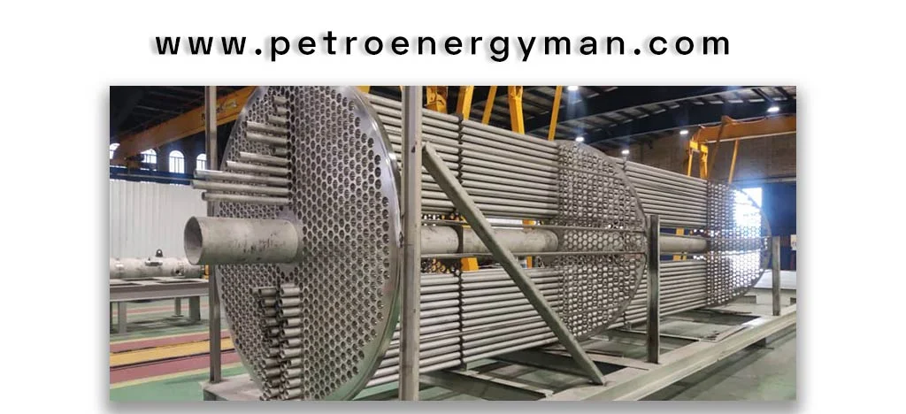
Nozzles
Nozzles serve as the inlet and outlet for the fluids entering and exiting the heat exchanger. The hot and cold fluids flow through separate nozzles and exit via dedicated outlets. The size of the nozzles can affect the pressure drop in the system.
Gaskets
In plate heat exchangers, each plate is equipped with a gasket responsible for sealing. These gaskets are made from materials resistant to high temperatures and corrosion (such as SBR, NBR, EPDM, Silicone, Viton). They form a tight, flexible seal between plates to prevent fluid mixing and maintain the integrity of the fluid pathways.
Plates
These heat exchangers consist of thin metal plates, either flat or corrugated, which create the flow channels. Hot and cold fluids flow in separate channels, and the narrow passageways create turbulence that enhances heat transfer efficiency due to the increased contact surface area.
Operation of Heat Exchangers
In a heat exchanger, the hot fluid enters one path (e.g., tubes) and the cold fluid enters another path (e.g., shell). Heat is transferred from the hotter fluid to the cooler fluid through the conductive wall separating them. This transfer occurs due to the temperature difference between the fluids and the thermal conductivity of the wall material. After the heat exchange, the fluids exit through separate outlets at changed temperatures.
The description of each component highlights that heat exchanger performance results from the complex synergy among parts. Baffles not only increase turbulence but also support the tubes, directly influencing efficiency and durability. Tube sheets hold the tubes and provide sealing. This interdependence means that the design and optimization of each component must consider its impact on the entire system, not just in isolation.
Reference to factors such as the difficulty of cleaning smaller tubes or the differences in maintenance between gasketed and brazed plate heat exchangers highlights that maintainability and ease of operation after installation are crucial considerations in heat exchanger design. Engineers do not focus solely on maximizing thermal efficiency; they also consider lifecycle costs, including installation, operation, maintenance, and repair. This comprehensive approach emphasizes the importance of designing for durability and serviceability alongside primary performance
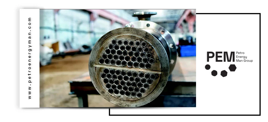
Conclusion
The heat exchanger is a key, multifunctional piece of equipment that plays a central role in numerous industrial processes. From oil and gas refineries to power plants, food and pharmaceutical industries, and the automotive sector, these devices are essential for heat transfer, efficiency improvement, energy optimization, and equipment protection. Their ability to transfer heat between fluids without direct contact makes them indispensable for maintaining process integrity and product quality.
Horizontal HRSG is recognized as one of the most advanced heat recovery systems used in power plants and heavy industries to enhance thermal efficiency and deliver stable steam production. This article outlines how the horizontal configuration—supported by optimized tube arrangements, cold-casing construction, modular architecture, and reliable operating performance—maximizes its integration with modern gas turbines. It also explores its industrial applications in combined-cycle power plants, petrochemical complexes, steel mills, refineries, and desalination units, while analyzing its key features, design parameters, performance factors, and economic considerations.
Horizontal HRSG
Horizontal Heat Recovery Steam Generator (HRSG) systems guide exhaust gases horizontally across vertical tubes. In this configuration, hot gases leaving the gas turbine enter the HRSG chamber horizontally and pass sequentially through different sections such as the superheater, evaporator, and economizer. The arrangement of the tubes is critical: tubes containing water and steam are positioned vertically within the horizontal gas flow. This tube layout allows horizontal HRSGs to maximize the benefits of natural circulation, ensuring efficient heat transfer and optimal boiler performance.
Technical and Economic Advantages of Horizontal HRSG
The horizontal HRSG design offers numerous operational and engineering benefits, making it ideal for integration with advanced gas turbines and enhancing overall efficiency.
Cold-Casing Design
One of the key features of horizontal HRSGs is the cold-casing design. In this configuration, the outer shell is fully insulated, and internal plates are attached with stainless steel to provide enhanced protection and stability.
• Thermal Expansion Control: Internal plates allow differential movement between the hot internal sections and the cooler outer casing, reducing channel expansion.
• High-Temperature Resistance: Ensures safe operation of the HRSG at elevated temperatures.
• Rapid Start-Up: Better management of thermal stresses allows the turbine to start without causing structural damage.
As a result, this design not only guarantees the stable operation of the HRSG but also makes it fully compatible with advanced gas turbines operating at high temperatures and high efficiency.

Enhanced Efficiency and Operational Performance
Horizontal HRSG systems, in addition to high heat recovery efficiency, provide significant operational benefits. The design of single-pass (HOT) models ensures easy temperature control and maintains efficiency even under partial load or high ambient temperatures. In advanced horizontal designs, especially the Once-Through type, operation at higher pressures than standard vertical boilers is possible, improving overall system performance.
Moreover, the horizontal layout allows easier access to internal sections such as the furnace, flue path, and drum, simplifying inspection and maintenance while reducing operational costs. The combination of flexibility, high-pressure capability, and ease of maintenance makes horizontal HRSGs a reliable and efficient choice for advanced power plants.
Construction and Installation
Horizontal HRSG systems are often designed in a modular format, which offers several operational advantages, especially for horizontal models. With modular design, boiler components are assembled in the factory before being transported to the installation site, reducing fabrication time and simplifying the production process.
On-site installation is also faster, easier, and safer using this approach. Additionally, the combination of horizontal gas flow, finned tubes, and compact design significantly reduces the installation footprint, operational costs, and overall project duration.
Industrial Applications of Horizontal HRSG
Horizontal HRSG systems are widely used as effective heat recovery and steam generation units due to their high reliability and customizable steam parameters across various industries.

Combined Cycle and Cogeneration Power Plants
Horizontal HRSG units are primarily employed in combined cycle power plants. In these systems, the waste heat from the gas turbine exhaust is converted into steam at the required pressure and temperature. This steam is then used to drive a separate steam turbine, significantly improving the overall thermal efficiency of the power plant.
In addition to electricity generation, horizontal HRSGs are extensively applied in combined heat and power (CHP / cogeneration) systems. Here, the generated steam not only powers the steam turbine but also serves industrial process needs, district heating networks, and heating requirements for production lines.
The horizontal design ensures that hot gases flow efficiently through all modules, finned tubes increase the heat transfer surface, and steam pressure is precisely controlled. These features optimize the performance of the unit in large power plants and complex industrial projects.
Specialized Industrial Applications
Horizontal HRSG units are used to recover waste heat in the oil, gas, and petrochemical industries. These systems can capture residual heat from very high-temperature sources, such as diesel engines or ash-laden furnaces, and convert it into steam with controlled pressure and temperature.
In heavy industries like refineries, petrochemical plants, steel, and cement factories, the generated steam is directly used for industrial processes, supporting stable operation of production lines.
Horizontal HRSGs also supply the necessary steam for water treatment and desalination plants, particularly in regions such as the Persian Gulf, where centralized energy resources are available.
From an operational capacity perspective, these HRSGs can operate in multi-pressure systems, supporting high-pressure steam production rates up to 480 tons per hour and operating pressures up to 15.4 MPa. These specifications demonstrate their ability to integrate with large gas turbines and reliably meet extensive industrial steam demands.

Key Features of Horizontal HRSG
Horizontal HRSGs possess several distinct features that make them suitable for specialized industrial applications:
Horizontal Gas Flow: Exhaust gases from the turbine pass horizontally through the tube assembly, which is why this type of HRSG is referred to as “horizontal.”
Vertical Heat-Exchange Tubes: Tubes carrying water and steam are arranged vertically to optimize flow and heat transfer.
Top Supported Design: Many horizontal tube designs are supported from the top, allowing thermal expansion to move freely downward and reducing thermal stresses.
Cold Casing Design: The HRSG outer casing remains cool thanks to internal insulation. This design helps control thermal expansion and minimizes internal stresses.
Material Variations: The use of high-strength steels such as T22 in the superheater and reheater sections reduces tube thickness and improves resistance to fatigue caused by thermal cycles.
Modular Design: Horizontal HRSG units are often designed modularly, enabling faster installation and up to 20% reduction in start-up time.
Factors Affecting Horizontal HRSG Design
In the design of a horizontally configured HRSG, a set of key factors must be thoroughly evaluated and considered.
Operational and Environmental Parameters
Several operational and environmental factors play a critical role in the design of HRSG systems.
Gas Turbine and HRSG Load: Design must be coordinated with the output of the gas turbine and the requirements of the steam turbine to ensure optimal performance.
Exhaust Gas Characteristics: Temperature, pressure, and flow rate of the exhaust gas influence the size and configuration of the HRSG.
Cyclic Operation: Horizontal HRSG units must withstand frequent start-ups, shutdowns, and load changes without compromising performance or reliability.
Water and Steam Conditions: The flow rate, pressure, and temperature of water and steam are crucial for stable operation and safe start-up.
Standards and Regulations: Compliance with steam velocity, pressure limits, and pressure vessel codes is essential for drum design and overall system safety.

Geometric and Mechanical Specifications
Finned Tube Arrangement and Dimensions: The layout and dimensions of finned tubes—including diameter, height, thickness, and tube configuration—directly determine heat-transfer efficiency and pressure drop.
Horizontal HRSG Overall Dimensions and Drum Size: Horizontal HRSG design depends heavily on the overall length, width, and height of the unit, as well as drum dimensions, to ensure stable and efficient performance.
Modular Design: A modular configuration enables faster installation and provides flexibility for both power generation and combined heat and power (CHP) applications.
Wall Thickness of Pressure-Retaining Components: The wall thickness of pressure-bearing parts affects thermal stress control and impacts overall start-up time and operational durability.
Performance and Efficiency Factors
Thermal Efficiency: Optimizing thermal efficiency is essential for improving overall productivity and minimizing energy losses across the system.
Horizontal HRSG Gas-Side Pressure Drop & Heat-Transfer Rate: Horizontal HRSG performance depends on reducing flue-gas pressure drop and maximizing heat-transfer rate, achieved through advanced finned-tube configurations and enhanced gas-flow management.
Tube Temperature and Steam Outlet Control: Precise control of tube temperatures and outlet steam conditions prevents material fatigue and ensures reliable, safe operation.
Desuperheater Steam Injection System: The steam injection system in the desuperheater regulates both pressure and temperature of the outlet steam for stable and efficient performance.
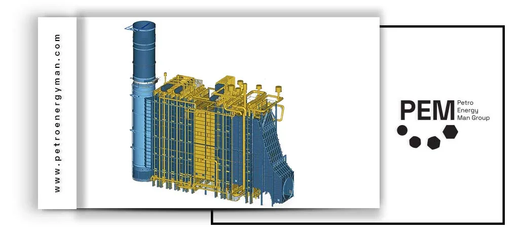
Economic and Reliability Factors
Initial Cost and Lifecycle Management: Optimizing the initial design and material selection plays a key role in reducing capital expenditure and minimizing long-term maintenance requirements.
Horizontal HRSG Reliability Performance: The reliability of a Horizontal HRSG directly impacts overall plant stability and operational efficiency, ensuring consistent performance under varying load conditions.
Overall System Optimization: Comprehensive integration of the HRSG design with the entire power plant supports seamless operation and enhances total system efficiency.
Conclusion
Horizontal HRSG serves as a strategic component within large-scale industrial facilities, and this article examined its critical aspects, including horizontal gas flow behavior, cold-casing structure, modular design advantages, major industrial applications, engineering characteristics, design considerations, and performance parameters. These capabilities enable the system to efficiently recover waste heat from gas turbines, generate stable steam across various pressure levels, and maintain reliable performance under demanding operating conditions. Ultimately, its ability to enhance energy efficiency, stabilize production processes, and reduce operational costs makes it an essential solution for modern power generation and high-demand industrial environments.
Industrial heat exchangers are devices that transfer thermal energy between two different fluids without allowing them to mix. This article explores the main types of industrial exchangers—including plate, shell-and-tube, and finned plate models. It also analyzes key parameters for selecting exchangers, operational challenges such as fouling, pressure drop, and corrosion, and the engineering solutions to address them. Furthermore, the industrial applications of these exchangers in chemical, power generation, food, and HVAC industries are discussed. To gain a deeper understanding of the technical details, advantages, and specialized applications of industrial heat exchangers, continue reading.
What is an industrial heat exchanger?
Industrial heat exchangers are devices engineered to transfer thermal energy between two different fluids—whether liquid or gas—without allowing them to mix. A conductive wall, typically made from metals with high thermal conductivity, separates the fluids and enables efficient heat transfer through the barrier.
The operation of an industrial heat exchanger relies on two primary mechanisms: conduction, where heat moves through the metallic wall, and convection, where the motion of the fluid transfers heat between the wall surface and the fluid itself. The flow paths and surface geometries are carefully designed to maximize temperature differences and contact area, ensuring the highest possible heat-transfer efficiency.
Industrial heat exchangers are manufactured in various configurations such as shell-and-tube, plate, air-cooled, and advanced custom-engineered models. These systems are essential in oil and gas facilities, petrochemical plants, power generation units, chemical processing lines, and food-industry applications. By enabling efficient heat recovery and precise temperature control, they contribute significantly to energy savings and the overall optimization of industrial processes.
If you are looking for more information about the applications of heat exchangers, their types, components, and more, you can visit the Industrial Heat Exchanger page and explore the technical details and practical guidance.
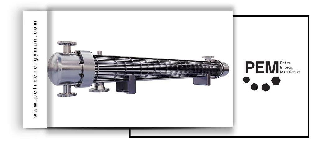
Types of Industrial Heat Exchangers
Get to know the different types of industrial heat exchangers used in exchanger industries.
Plate Heat Exchangers
Plate heat exchangers are built from a series of thin, corrugated plates that separate the hot and cold fluid streams. These plates include corner ports for fluid entry and exit, and they are arranged so that the two fluids flow alternately between them. This structure increases the heat-transfer surface area and creates controlled turbulence, significantly improving thermal performance. Due to their easy maintenance and quick cleaning, plate heat exchangers are widely used in the food and pharmaceutical industries. They are also available in different configurations—such as gasketed and spiral plate models—each engineered for specific fluid conditions and thermal requirements.
Shell and Tube Heat Exchangers
industrial heat exchangers, particularly shell-and-tube systems, are widely used thanks to their design flexibility and ability to handle high temperatures and pressures in petrochemical plants, power stations, and processing facilities. These units consist of a cylindrical shell that contains a bundle of tubes. One fluid flows inside the tubes, while the other passes through the shell side, enabling heat transfer through conduction and convection. To enhance efficiency and minimize unwanted flow stagnation, internal baffles are installed to direct the shell-side fluid, increase heat-transfer coefficients, and maintain uniform flow distribution. The geometry of the tubes and baffles, flow rate, and temperature difference between fluids are critical factors that determine thermal efficiency and pressure performance.
For specialized consultation on heat exchanger design, fabrication, and engineering solutions, contact Petro Energy Man at 02157423.
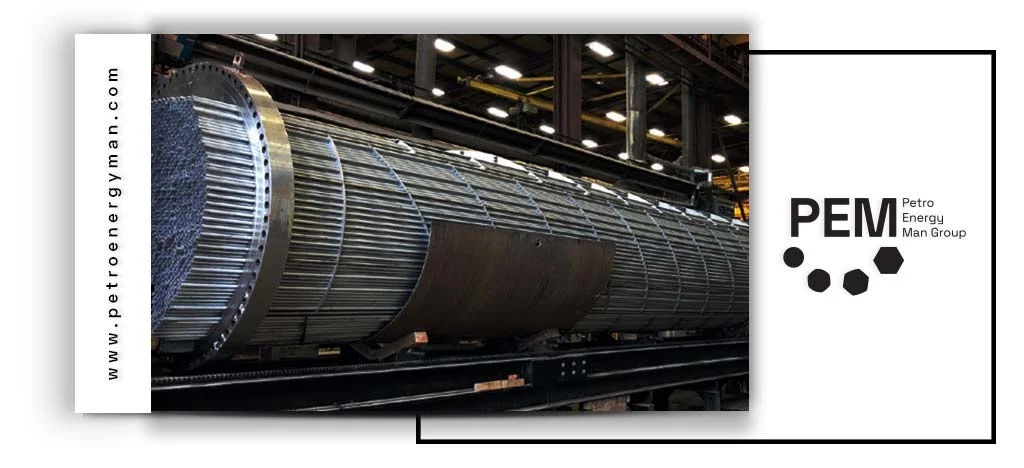
Fin Plate Heat Exchangers
industrial heat exchangers like fin plate heat exchangers are engineered with flat plates and corrugated fins that keep the two fluid streams separate while enabling highly efficient surface-based heat transfer. The fins expand the effective contact area and guide the fluid flow into controlled turbulence—enhancing heat transfer without creating excessive pressure drop or stagnant zones.
This configuration boosts the overall heat-transfer coefficient, reduces thermal resistance, and ensures uniform temperature distribution across the unit. Thanks to their high surface-area-to-volume ratio and lightweight structure, fin plate heat exchangers are ideal for applications with strict space or weight constraints such as cooling systems in heavy-duty vehicles, cargo machinery, and aircraft. The engineered fin geometry and plate arrangement also deliver strong mechanical stability, easy cleaning, and simplified maintenance. Another advantage is their ability to operate effectively under high temperature differences and medium-to-high pressures, making them suitable for low-density fluids or high-velocity flow conditions.
The Heat Exchanger Design page provides detailed explanations, measurement methods, and design standards used in the heat exchanger industry, covering in-depth engineering criteria from thermal design calculations to mechanical considerations.
Key Parameters for Selecting Industrial Heat Exchangers
• Operating Temperature and Pressure of Fluids: The choice of exchanger type and the thickness of tubes or shell directly depend on the pressure and temperature, which is a standard design principle.
• Fluid Viscosity and Properties: High viscosity increases pressure drop, while deposition and corrosion influence material selection and cleaning design; these considerations follow API and TEMA standards.
• Flow Rate and Phase Change: Fluid flow rate and phase (single-phase or two-phase) affect tube diameter, exchanger type, and heat transfer coefficient; this is a fundamental principle in heat transfer engineering and exchanger design.
• Thermal and Mechanical Characteristics: Overall heat transfer coefficient (U-value), effective temperature difference (ΔT or LMTD), and wall pressure are key parameters in thermal and mechanical design.
• Material and Corrosion Considerations: Material selection is based on thermal conductivity, chemical resistance, mechanical stability, and cost; this is a standard engineering requirement.
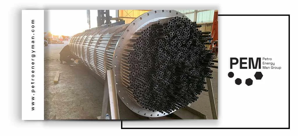
Operational challenges and solutions of industrial heat exchangers
Fouling, pressure drop, and corrosion are among the main challenges of industrial heat exchangers; the following sections discuss each of them and present engineering solutions to address these issues.
Fouling
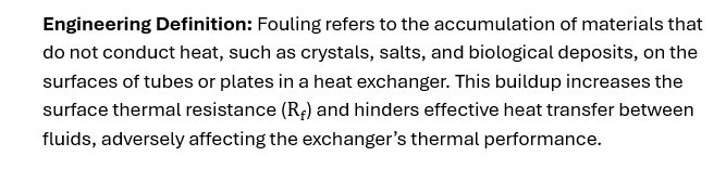
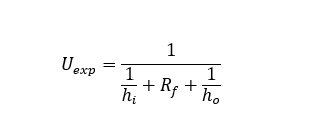
Engineering Solutions: Several strategies can be implemented to mitigate fouling:
• Scheduled Periodic Cleaning: Perform maintenance according to SOPs based on operational data to prevent harmful buildup.
• Chemical Cleaning: Use acids, alkalis, and corrosion inhibitors with precise pH and dosage control to dissolve deposits.
• Mechanical Cleaning: Employ tools such as calerings, pigging, or scrubbers to remove physical deposits.
• Fouling Factor Monitoring: Install thermal sensors and measure temperature differences to determine the optimal cleaning intervals and prevent efficiency losses.
Pressure Drop
Engineering Solutions:To minimize pressure drop and maintain optimal performance, engineers use the following strategies:
- Geometric Optimization: Increase tube diameters, reduce flow path length, and adjust the number of passes to lower flow resistance.
- Flow Control: Use manifolds in plate exchangers to prevent dead zones and ensure uniform flow distribution.
- CFD Modeling: Simulate fluid flow to predict pressure drop and design optimized flow channels, balancing heat transfer efficiency with pressure loss.
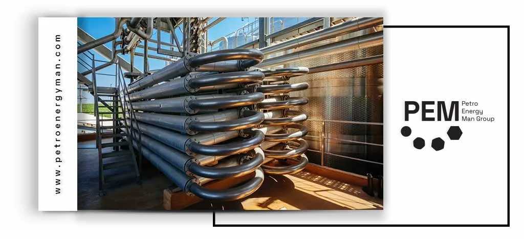
Corrosion
Industrial heat exchangers can experience corrosion, defined as the deterioration of exchanger materials due to chemical reactions between the tube or shell surfaces and the working fluid. This phenomenon leads to wall thinning, reduced mechanical strength, and decreased heat transfer efficiency, potentially impacting both thermal performance and equipment safety.
Consequences: Severe corrosion can cause mechanical failure, reduce the service life of the exchanger, and increase the risk of leaks or equipment downtime. Over time, it also significantly raises maintenance and replacement costs.
Engineering Solutions:To mitigate corrosion effects, engineers implement the following strategies:
- Alloy Selection: Use titanium in highly corrosive environments and high-temperature conditions, and nickel-based alloys (Hastelloy) for acidic fluids and temperatures above 300°C.
- Thermally Efficient Materials: In non-corrosive conditions, brass or bronze tubes are chosen to maintain good heat transfer while providing adequate resistance.
- Fluid Chemistry Control: Adjust pH levels and add corrosion inhibitors to the fluid to slow degradation and extend the exchanger’s service life.
Applications of Industrial Heat Exchangers
Exchanger industries depend on industrial heat exchangers for efficient thermal management across diverse process applications:
Chemical and Petrochemical Industries
In chemical processes, industrial heat exchangers play a critical role in temperature control, ensuring operational stability and product quality. Within reactors, maintaining a constant temperature is crucial to control reaction rates and prevent severe thermal fluctuations. During distillation and vapor condensation stages, these exchangers create optimal temperature conditions, enabling precise separation of compounds based on boiling points. After reactions, they are used for cooling products, ensuring operational safety and preventing material degradation or quality loss. Thus, industrial heat exchangers are vital throughout production—from initiating reactions to stabilizing the final product.
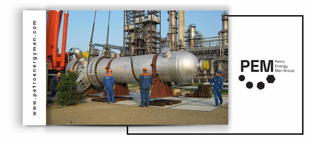
Power Generation and Power Plants
In power generation, industrial heat exchangers are key to enhancing the performance of thermal systems. In steam and combined-cycle power plants, they are used for condensing turbine exhaust steam and preheating feedwater for boilers. These processes not only improve the plant’s thermal efficiency but also reduce fuel consumption and optimize the overall energy production system.
Food and Beverage Industries

HVAC Systems
In commercial and industrial buildings, industrial heat exchangers are used for precise temperature control and to facilitate heat transfer between cold and warm air streams. By optimizing heat transfer and managing airflow, these systems enhance the energy efficiency of HVAC units, reduce thermal and cooling loads, and ultimately lower operational costs while improving overall system performance.
Wastewater Treatment and Energy Recovery
Industrial heat exchangers enable the recovery of heat from wastewater, which can then be used to preheat incoming streams or provide the necessary temperature for biological reactions. Utilizing these systems leads to significant energy savings, enhances the performance of treatment processes, and plays a crucial role in reducing operational costs while improving overall operational efficiency.
Conclusion
Industrial heat exchangers play a crucial role in heat transfer and energy optimization across industrial processes. This text covered the main types of heat exchangers, key selection parameters, and common operational challenges such as fouling, pressure drop, and corrosion—along with the engineering solutions to address them. Proper use of these systems leads to higher efficiency, lower operational costs, and improved safety and process stability.
Heat exchangers manufacturers are essential in industries like oil, gas, petrochemical, and power. Among them, Petro Energy Man (PEM) has a long history, starting with civil engineering projects and gradually expanding into a full-service engineering, procurement, and construction company. In this article, we look at PEM’s manufacturing standards, how it designs and builds heat exchangers, and how it meets the specific needs of its customers. We also provide an overview of other notable heat exchanger manufacturers in Iran and around the world. Continue reading to understand how PEM delivers reliable and efficient heat transfer solutions.
Petro Energy Man (PEM) – Heat Exchangers Manufacturers
Petro Energy Man Group (PEM) began its operations in 1975. In its early years, the company primarily focused on executing civil projects and providing related technical services — a path that laid the foundation for PetroMan’s strong and successful presence in the nation’s construction sector.
Strategic Development and Entry into Power Plant Industries
A major turning point in PEM’s growth came in 1976 with its entry into power plant projects. This milestone was achieved through strategic collaborations and the acquisition of technical expertise from international partners such as Brown Boveri and Asseck.
Through a deliberate strategy of targeted specialization, PetroMan systematically expanded its scope of operations over the following decades. By the mid-1990s, the company had successfully evolved beyond civil construction and established itself as a comprehensive EPC (Engineering, Procurement, and Construction) contractor, actively operating in key sectors including oil, gas, petrochemical, power generation, and cement industries.
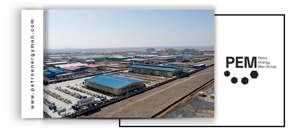
Standardization and Current Capabilities
Today, Petro Energy Man stands as a capable and certified contractor, officially recognized by the Planning and Budget Organization of Iran. This formal accreditation serves as a testament to the company’s high capacity and technical expertise in delivering large-scale industrial megaprojects across the country’s infrastructure sectors.
By maintaining strict adherence to international quality standards, PetroMan has earned the lasting trust of a wide range of prominent domestic and international clients.
Strategic Network and Sustainable Competitive Advantage
Petro Energy Man plays a role that extends far beyond that of a traditional EPC contractor. The group has firmly positioned itself at the core of the professional network of heavy industries and the energy sector. Its active membership in key national institutions and associations stands as a testament to the company’s knowledge base, credibility, and enduring commitment to excellence. Strategic Memberships:
- Technical and Engineering Associations: Including the Mechanical Engineering Association, Engineering Standards Association, and the Technical Department of University of Tehran Alumni, ensuring continuous access to the latest innovations and scientific expertise.
- Professional and Contracting Bodies: Such as the Syndicate of Construction Companies and the Construction Services Industry Association, reflecting commitment to national execution standards and professional ethics.
- Industry Associations: To maintain a dynamic connection with current market demands and high-level industrial policymaking.
Human Capital and Project Management Infrastructure
PetroMan’s strength lies in its specialized human capital. The company’s internal team comprises over 200 experienced professionals across five key areas: management, engineering, supply chain, supervision, and execution, working synergistically.
This team, in close collaboration with four active subsidiary companies, forms an integrated and flexible operational structure. This organizational architecture enables Petro Energy Man to execute projects — regardless of scale or complexity — with the highest standards and guaranteed quality.
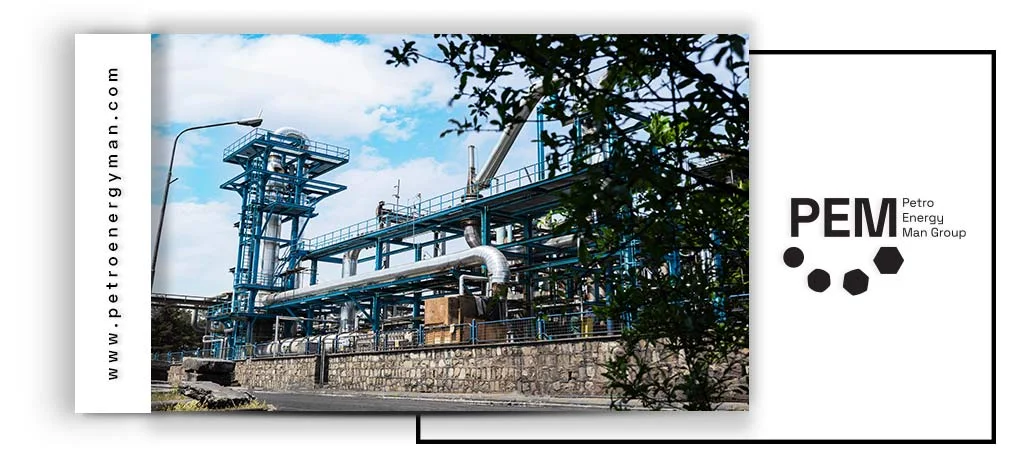
Distinguished Services
Another key advantage of Petro Energy Man lies in its provision of comprehensive pre-commissioning and full commissioning services. These services ensure that clients receive their facilities and projects fully operational, tested, and ready for production, thereby minimizing transfer risks and potential delays in the start of operations.
Heat Exchanger Standards Applied by Petro Energy Man
For specialized applications in the oil, petrochemical, and natural gas industries, Petro Energy Man adheres to the following ISO standards:
- ISO 16812: This standard applies to shell and tube heat exchangers, including heaters, condensers, coolers, and reboilers, used in the oil, petrochemical, and natural gas industries.
- ISO 13706: This standard defines the requirements and recommendations for the design, materials, fabrication, inspection, testing, and preparation for shipment of air-cooled heat exchangers used in oil, petrochemical, and natural gas applications.To ensure consistent quality and manufacturing processes, Petro Energy Man also complies with quality management standards:
- ISO 9001:2015: This international standard for quality management systems ensures stable product quality across heat exchanger production facilities. It is also applied in the manufacturing of plate heat exchangers.
- ISO 29001: This standard is a sector-specific quality management system designed for the oil, petrochemical, and natural gas industries.
Custom Heat Exchanger Fabrication
At PetroEnergy Holding, we focus on the design and fabrication of heat exchangers precisely tailored to the specific requirements of each industrial operation. This expertise covers a wide range of sectors, including chemical, pharmaceutical, biotechnology, food processing, and refineries. Each exchanger is designed and manufactured based on operational specifications, working conditions, and required thermal parameters to ensure both efficient heat transfer and the mechanical strength needed for demanding industrial environments.
The PetroEnergy engineering team, leveraging advanced simulation tools, specialized knowledge, and extensive practical experience, analyzes the unique needs and challenges of each system to provide the optimal design solution. This engineering approach ensures that the fabricated heat exchangers are not only thermally efficient but also durable and reliable over the long term.
Partnering with PetroEnergy provides access to precise, custom-engineered solutions that maintain the performance, efficiency, and safety of thermal systems over time while enhancing the stability of industrial operations.
How PEM Meets Customer-Specific Requirements
In general, the following stages are carried out at PEM, from design to execution, in the fabrication of a heat exchanger.
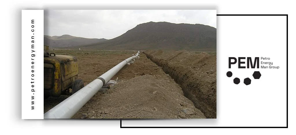
Data Collection for Equipment Design
In this stage, all necessary design information is gathered, which can be extracted from the process datasheets provided by the client. The collected data include:
- Specifications of the hot and cold fluids
- Operating temperatures and pressures for both hot and cold sides
- Thermodynamic properties of the fluids, including density, viscosity, and heat transfer coefficients
- Fouling factors for both hot and cold fluids
- Allowable pressure drops and flow velocities on the shell and tube sides, which must be considered during the design process
Process Simulation
At this stage, heat exchanger simulation is carried out, marking the beginning of the design phase. In addition to the thermal design, which determines the required heat transfer area and heat duty, a hydraulic simulation is also performed.
Using the constraints of fluid velocity and pressure drop for both the hot and cold sides, parameters such as tube length, inner diameter, and outlet temperatures of the fluids are calculated to achieve optimal performance and efficiency.
Mechanical Design
At this stage, based on the data obtained from the previous phase and in accordance with ASME Section VIII and TEMA (Tubular Exchanger Manufacturers Association) standards, key parameters within the heat exchanger design—such as shell thickness, tube thickness, flange and gasket dimensions, bolts and nuts, and other components—are calculated. Finally, the total equipment weight is determined.
Thorough knowledge and understanding of these design standards play a crucial role in achieving an optimized and reliable mechanical design.
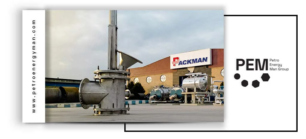
Drawing the Different Parts of the Heat Exchanger
Drawing the different parts of the heat exchanger for procurement and fabrication. These drawings include the following:
- General Drawing
- Tube Bundle Drawing
- Sectional Plan
- Detail Accessories
- Weld/NDT Map
- Tube Sheet Layout
Additionally, a Part List Drawing is prepared in which all components of the heat exchanger are identified with unique reference numbers. The entire process — from design to execution — for all heat exchangers and other fabricated equipment at PEM (Petro Energy Man) is carried out under a unified engineering procedure, with full coordination between the various engineering departments.
Other Heat Exchangers Manufacturers
Fateh Sanat Company: Fateh Sanat is one of the leading heat exchangers manufacturers in the petrochemical industry. The company plays a key role in optimizing heat transfer processes and minimizing energy loss through its high-quality products. Its heat exchangers are specifically designed to meet the demanding requirements of the petrochemical sector and are well-recognized in both domestic and international markets.
Nasim Mobadel Industrial Group: Founded in 1985, Nasim Mobadel Industrial Group has been a major producer of heat exchangers in Iran. Utilizing advanced equipment and modern technologies, the company manufactures and supplies a wide range of shell and tube and air-cooled heat exchangers to both local and foreign markets.
Sana Mobadel Tose’e Pars Company: Heat exchangers manufacturers such as Sana Mobadel Tose’e Pars Company play a crucial role in supporting industrial and petrochemical sectors. Sana Mobadel Tose’e Pars is an active manufacturer specializing in heat exchangers for petrochemical industries, boilers, and plate heat exchangers. Relying on the expertise of its skilled engineers, the company has significantly contributed to reducing the nation’s dependence on imported equipment.
By adhering to global standards and maintaining a commitment to continuous innovation, Sana Mobadel Tose’e Pars has earned the trust of domestic and international markets, solidifying its position as a leading industrial manufacturer in the region.
Fan Gostar Pouya: Fan Gostar Pouya Company is active in producing various types of heat exchangers for the petrochemical industry and air-cooled systems. With advanced technologies and high standards, the company’s products play a key role in heat transfer processes and in reducing energy loss in petrochemical operations.
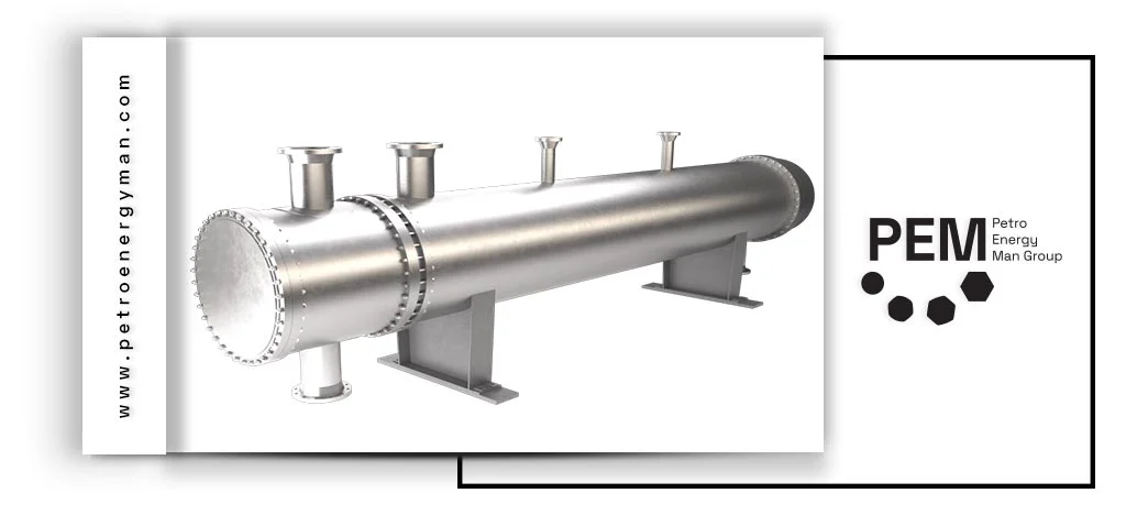
Heat Exchanger Manufacturers Worldwide
Some of the leading heat exchanger manufacturers globally include:
- APV: A manufacturer of plate heat exchangers and a subsidiary of SPXFLOW. The company’s founder, Dr. Richard Seligman, is recognized as the inventor of the heat exchanger.
- Alfa Laval: A Swedish company and one of the leading plate heat exchanger manufacturers in the world.
- THT: A Chinese company specializing in the production of plate heat exchangers.
- Kelvion: A German brand established in 1920, formerly known as GEA. Kelvion is one of the world’s leading heat exchanger manufacturers.
- Danfoss: Danfoss is also recognized as a major global manufacturer of heat exchangers.
High Pressure Heat Exchanger Manufacturer
A high-pressure heat exchanger is a specialized equipment designed to operate under conditions where fluids flow at very high pressures. These types of exchangers play a critical role in industries where high-pressure boilers are an integral part of production or operational systems. The primary function of these units is to transfer heat between fluids at different temperatures safely and separately, ensuring no mixing occurs and maintaining stable performance under high pressure.
Designing and manufacturing high-pressure heat exchangers requires advanced technical expertise and the use of high-quality materials to withstand mechanical forces from internal and external pressures, while ensuring long-term stability and safety of the boilers.
Given the critical importance and design complexity of these units, selecting a reputable manufacturer for high-pressure heat exchangers is essential. In the following section, we outline the key factors to consider when choosing a reliable manufacturer for such equipment.
Key Factors in Choosing a High-Pressure Heat Exchanger Manufacturer
Selecting a manufacturer for high-pressure heat exchangers is a critical decision that directly impacts the efficiency, safety, and long-term operational costs of a project. Issues such as leak in shell and tube heat exchanger—which often result from poor design, inadequate material selection, or substandard fabrication—highlight the importance of choosing a qualified and experienced manufacturer with strong expertise and experience, reliable design and engineering capabilities, compliance with standards and certifications, advanced testing and inspection facilities, and the ability to deliver custom manufacturing solutions. To make the best choice, several key factors should be considered.
Compliance with Standards and Certifications
A reputable manufacturer should produce equipment in accordance with international standards for high-pressure systems. Standards such as ASME BPVC Section VIII for pressure vessel design and construction, TEMA for shell and tube heat exchangers, and API 660 for industrial heat exchangers in the oil and gas sector are among the most important. Obtaining recognized certifications demonstrates the manufacturer’s commitment to quality and safety.
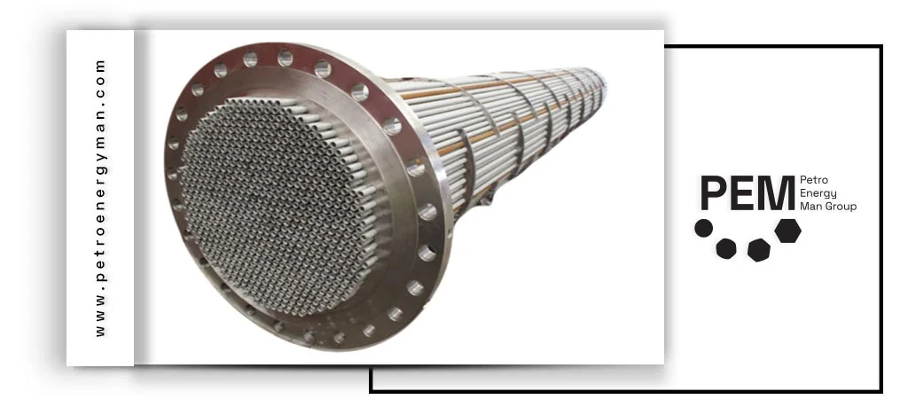
Design and Engineering Capabilities
A leading manufacturer must have strong design and engineering capabilities. This includes using specialized heat exchanger design software such as HTRI and Aspen EDR to accurately simulate flow, temperature distribution, and pressure drop. These capabilities help optimize dimensions, reduce pressure losses, and enhance the thermal efficiency of the heat exchanger.
Testing and Inspection Facilities
The manufacturer should have adequate facilities to perform thorough post-production testing. These tests include hydrostatic pressure testing, leak tests, thermal performance testing, and non-destructive inspections (NDT) such as UT, RT, or PT to ensure the integrity of welds and the internal structure of the heat exchanger.
Custom Manufacturing Capability
Given the diverse needs of various industries, a manufacturer’s ability to design and fabricate custom heat exchangers based on specific technical requirements is a significant competitive advantage. This capability ensures that the heat exchanger aligns optimally with the operational system.
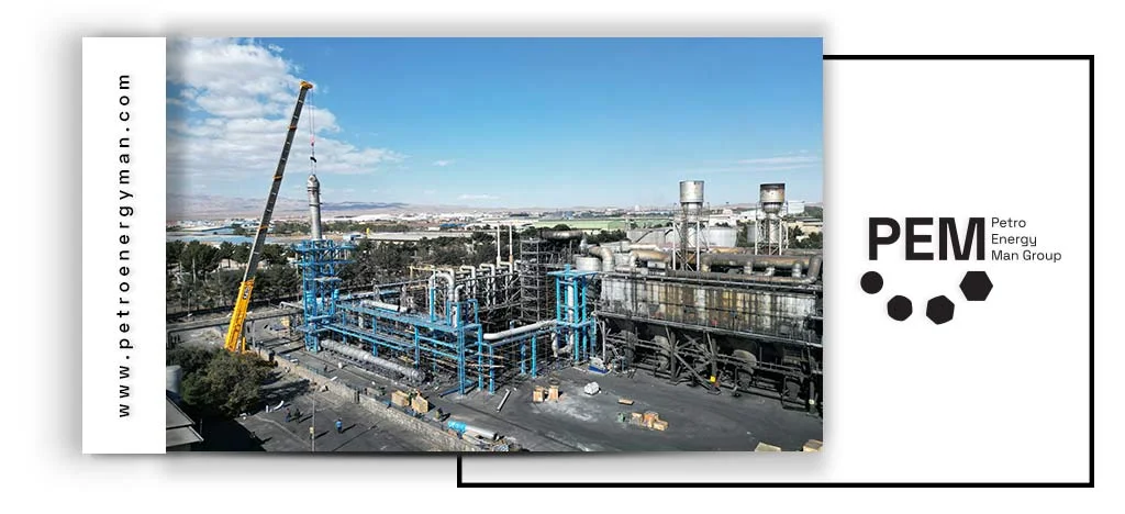
Expertise and Experience
Manufacturers with extensive experience in designing and producing high-pressure heat exchangers possess the knowledge and technical skills necessary to address complex engineering challenges. Their ability to provide specialized consultation and deliver customized designs for specific operational conditions is crucial. Companies with a proven track record of successful high-pressure heat exchanger projects in similar industries are generally more reliable and reputable.
Conclusion
Heat exchangers manufacturers such as Petro Energy Man (PEM) and other leading global companies play a vital role in industrial processes. In this text, we discussed PEM’s history, strategic development, compliance with international standards, detailed design and fabrication processes, and key services including commissioning. We also covered other notable Iranian and global manufacturers and their contributions to the industry, showing how these companies combine high-quality equipment with technical expertise to support complex industrial operations.
leak in shell and tube heat exchanger does not merely mean fluid loss. This phenomenon can lead to a significant reduction in thermal efficiency and increased operational costs, as the heat transfer rate may decline due to fluid mixing or an inadequate effective heat exchange surface. Moreover, if flammable or toxic fluids are involved, serious safety and environmental hazards arise, including risks of explosion and contamination.
Leakage can also damage downstream equipment and ultimately cause unplanned shutdowns of the entire process. The complex structure of these exchangers, which includes two separate circuits (shell and tube) and limited access to internal tubes, makes troubleshooting a highly specialized and precise task. Therefore, understanding failure mechanisms and employing appropriate leak detection methods is essential to ensure operational stability and safety.
Leak in Shell and Tube Heat Exchanger: Root Cause Analysis
Effective leak detection requires identifying the root causes and mechanisms that lead to failure. These mechanisms often result from mechanical, chemical, and thermal stresses experienced by the exchanger during its operational life.
Corrosion and Erosion
Corrosion is one of the most common causes of failure in heat exchangers. It can manifest in various forms, including pitting corrosion and crevice corrosion. For example, the presence of chloride ions in the fluid can damage the protective layer of stainless steel, leading to sudden and rapid corrosion.
Another destructive factor that often acts synergistically with corrosion is fouling. Fouling refers to the accumulation of unwanted materials such as deposits, polymers, and inorganic salts on heat transfer surfaces, which can impair exchanger performance even in small amounts. This deposit buildup initiates a destructive cause-and-effect chain. As the flow cross-section narrows due to fouling, fluid velocity locally increases in certain areas of the exchanger. This localized velocity increase accelerates metal erosion, removing protective surface layers and exposing the base metal to intensified corrosive attack. This erosion reduces the metal’s resistance to corrosion and sets the stage for corrosion-induced failures. Therefore, fouling should not be viewed solely as a thermal efficiency issue but also as a major contributor to mechanical and chemical failures.
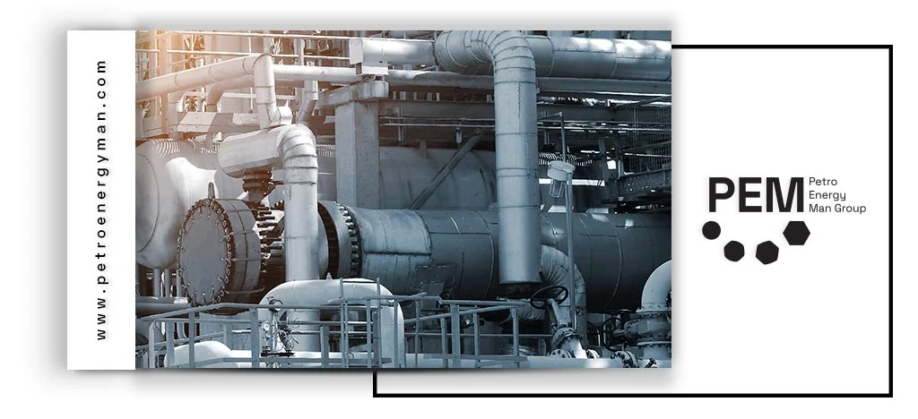
Fatigue and Stress
Leak in Shell and Tube Heat Exchanger often occurs due to thermal and mechanical stresses. Thermal fatigue arises from repeated heating and cooling cycles and significant temperature differences between the shell and tubes, causing physical expansion and contraction.These continuous dimensional changes gradually compromise the integrity of the tube-to-tube-sheet connection, potentially leading to microcracks and, ultimately, leakage.
Mechanical fatigue, on the other hand, occurs due to cyclic loads over time. These repeated loads, even at stress levels below the material’s yield strength, can initiate and propagate microscopic cracks, eventually resulting in complete component failure.
One particularly destructive mechanical phenomenon is water/steam hammer. This occurs due to sudden changes in fluid velocity (e.g., from the rapid closure of a valve), generating a high-pressure wave. This immense force can rupture or collapse the tubes and shell. Additionally, vibrations caused by fluid flow or external sources can exert significant forces on the tubes, leading to failure or loss of sealing.
Manufacturing and Assembly Defects
Defects from manufacturing or assembly processes are also common causes of leakage. These may include physical damage during transport or improper installation, particularly when reinstalling the tube bundle. Sensitive points prone to defects include the tube-to-tube-sheet joint, which can experience roll leaks. Faulty gaskets, washers, or loose bolts and screws are also major contributors to heat exchanger leakage.
Heat Exchanger Leaks: Detection Methods
Shell and tube heat exchanger leak test is a systematic process that begins with visual inspection and continues with pressure and advanced non-destructive testing (NDT) methods.
| Method | Description | Advantages | Disadvantages |
|---|---|---|---|
| Visual Inspection | Checking for cracks, corrosion, erosion, or gasket failure using direct observation and operational data. | Simple, fast, low cost. | Cannot detect internal or microscopic leaks. |
| Hydrostatic Test | Filling one side with water and applying 1.3× working pressure to check for visible leaks or pressure drop. | Safe, verifies structural integrity, widely accepted. | Time-consuming, needs large water volume, may miss tiny leaks. |
| Pneumatic Test | Uses compressed air or nitrogen at 1.1× pressure; leaks found via soap-bubble solution or pressure drop. | Fast, no drying required, detects very small leaks. | High explosion risk, only for special cases. |
| Helium Leak Detection | Injects helium and uses a mass spectrometer to detect microscopic leaks on the low-pressure side. | Extremely accurate, quantifies leak rate, ideal for critical systems. | Expensive equipment and setup required. |
| Fluorescent Dye Penetrant | Tracer dye added to system; leaks glow under UV light for visual detection. | Detects fine surface leaks; easy visualization. | Not suitable for internal or high-temperature areas. |
| Eddy Current Testing (ET) | Electromagnetic probe detects tube wall thinning, corrosion, or cracks. | Non-destructive, fast, ideal for periodic inspection. | Only for conductive materials, needs skilled operator. |
| Ultrasonic Testing (UT) | Uses sound waves to detect subsurface flaws or measure wall thickness. | Accurate depth measurement, detects hidden defects. | Needs access to both sides or good coupling surface. |
| Acoustic Emission Testing (AE) | Detects real-time ultrasonic signals from active cracks or leaks. | Can be used during operation; detects active defects. | Complex analysis, expensive sensors. |
Visual Inspection and Operational Data Analysis
Before any high-pressure testing, the first step is a thorough visual inspection. The inspector should look for signs of physical damage such as cracking, perforation, corrosion, and erosion on the shell, tubes, nozzles, and welded joints. The condition of the foundation, supports, and gaskets should also be examined. Alongside visual inspection, analyzing operational data is highly important. Abnormal pressure drops on the shell or tube side, as well as noticeable reductions in heat transfer efficiency, are early indicators of potential internal leakage or fouling.
Pressure Testing
Pressure tests are the most common and fundamental methods used in shell and tube heat exchanger leak detection, allowing inspectors to identify internal and external leak paths.
Hydrostatic Test
Leak in Shell and Tube Heat Exchanger is commonly detected using a hydrostatic test, which involves completely filling one side of the exchanger (shell or tube) with water and fully venting any air.Pressure is then increased to 1.3 times the maximum operating pressure or at least 1.5 times the design pressure and held for a specified duration (about 30 minutes). During this time, any pressure drop or visible water leakage at suspect points indicates a leak. For shell testing, components such as the shell cover and channel cover are removed, and a test ring is used to apply pressure to the shell. This method allows detection of shell cracks or holes, faulty gaskets, and loose bolts.
Advantages: Due to the incompressibility of the liquid, this method is very safe. The energy stored in water is minimal, so in case of failure, there is no risk of explosion, and the pressure is quickly relieved. Hydrostatic testing also evaluates the overall strength of the component against design pressure.
Disadvantages: This method is time-consuming, requires pumps and large volumes of water, significantly increases the exchanger’s weight, and after testing, complete drainage and drying are necessary. It may also lack sufficient sensitivity to detect very fine leaks.
read more: Plate Heat Exchanger
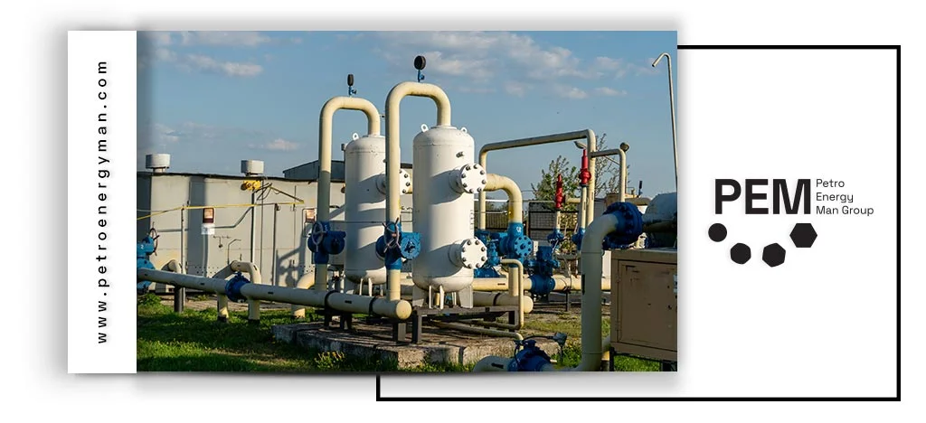
Pneumatic Test
When water cannot be used, a pneumatic test is employed. In this method, air or an inert gas such as nitrogen is injected into the exchanger, and pressure is increased up to 1.1 times the maximum operating pressure. Leaks are identified using a soap bubble solution applied to suspected points. Precise monitoring of the pressure gauge can also record any pressure drop as evidence of internal or external leakage.
Advantages: This test is quick and easy due to the use of gas, requires no drainage, and, because of the small molecular size of gases, has higher sensitivity for detecting fine leaks compared to hydrostatic testing.
Disadvantages and Risks: Due to the high potential energy stored in compressed gases, this method carries a significant risk of explosion. In case of failure, this energy is released suddenly, which can result in projectile hazards and serious personal or financial damage. Therefore, pneumatic testing should only be conducted in emergency situations and under the strictest safety protocols
Read More: Shell And Tube Heat Exchanger
Tracer-Based Methods
These methods are used to detect leaks that cannot be identified through traditional pressure tests.
Helium Leak Detection
This method is considered the most precise leak detection technique. It works by using helium as an inert, non-toxic, and non-flammable tracer gas. Due to its very small atomic size, helium can easily pass through the tiniest pores. During testing, helium is injected into one side of the exchanger (the higher-pressure side), and any escaping helium molecules are detected on the other side using a mass spectrometer.
This level of precision is essential for critical applications where even microscopic leaks can have catastrophic consequences. For example, in hydrogen-service heat exchangers, the API 660 standard mandates helium leak detection. This method not only confirms the presence of leaks but also measures the exact leakage rate, allowing engineers to predict the remaining life of the exchanger and plan the optimal time for repair or replacement. Required equipment includes a mass spectrometer, vacuum pump, and helium recovery system.
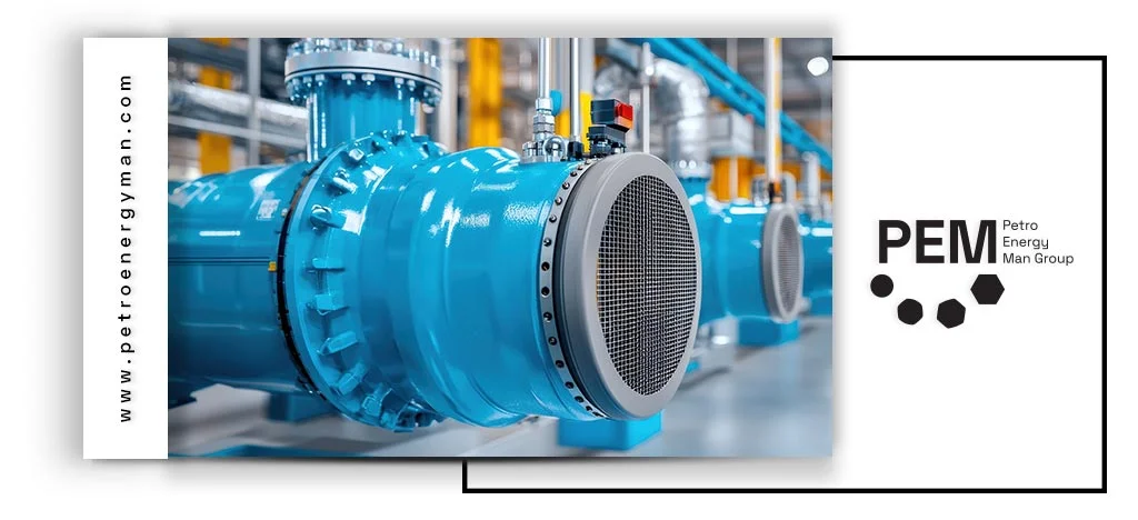
Fluorescent Dye Penetrant
This method involves injecting a tracer liquid containing fluorescent dye into the exchanger fluid (typically oil). After some time, a UV flashlight is used on the external surfaces, revealing the precise leak locations through the glowing dye (usually yellow or green). This method is suitable for detecting very fine leaks and, due to its ease of use, is widely applied in industries such as automotive cooling systems. In some industrial formulations, the dye may also change color upon contact with water or steam.
Advanced Non-Destructive Testing (NDT) Methods
These methods allow inspectors to detect internal tube defects without fully disassembling the heat exchanger.
- Eddy Current Testing (ET): This test uses an electromagnetic probe to induce eddy currents in the tubes. Any defect or wall thinning in the tubes disrupts these currents, which is detected by the device. This method is ideal for periodic and preventive inspection of tubes to identify wall thinning, corrosion, and cracks.
- Ultrasonic Testing (UT): This method sends high-frequency sound waves and analyzes their reflections to detect internal and subsurface defects such as cracks, as well as to measure tube thickness for corrosion monitoring.
- Acoustic Emission Testing (AE): A passive and dynamic method that detects ultrasonic waves generated by internal sources within the material (such as crack propagation or active leaks) as they occur. The main advantage of this method is the ability to perform online monitoring and detect defects while the heat exchanger is in normal operation.
Leak in Shell and Tube Heat Exchanger: Operational Guide
The leak detection process requires strict adherence to operational steps and safety protocols.
Preparation Before Testing
- Isolation: The heat exchanger must be completely disconnected from the main system. This can be done by closing isolation valves or physically separating it from the process lines.
- Fluid Drainage: Both the shell and tube sides must be fully drained and cleared of any fluid.
- Initial Inspection: Before applying any pressure, a thorough visual inspection should be conducted to identify suspicious areas or visible damage.
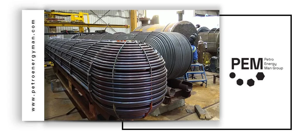
Leak Test Protocols
- Shell Test: In this procedure, the shell of the heat exchanger is filled with water. Components such as the shell cover and channel cover are opened, and after installing the test ring and performing venting, the exchanger is subjected to hydrostatic pressure. During the test, the inspector observes and records defects such as cracks, holes, or leaks from gaskets.
- Tube Test: This test can be performed separately or in combination with the shell test. In this case, the tube side of the exchanger is pressurized, and leaks at the tube-to-tubesheet connections (roll leaks) or the tube walls are examined.
Safety Protocols for Pressure Testing
It is important to note the fundamental difference in safety hazards between hydrostatic and pneumatic testing. While both involve high pressure, the nature of the test fluid significantly affects the level of risk. Water, due to its incompressibility, stores very little energy. Therefore, in the event of a failure, the pressure is released quickly with minimal hazard.
In contrast, in pneumatic testing, compressed gases such as nitrogen store enormous potential energy. If a defect or failure occurs, this energy is released suddenly, potentially causing explosions or the ejection of parts, posing serious safety and financial risks. For this reason, pneumatic testing is recommended only when the use of water is impossible and must be conducted under the strictest safety protocols, including explosion-proof equipment, precise pressure regulators, and full personal protective equipment (PPE) such as safety glasses, helmets, gloves, and appropriate workwear.
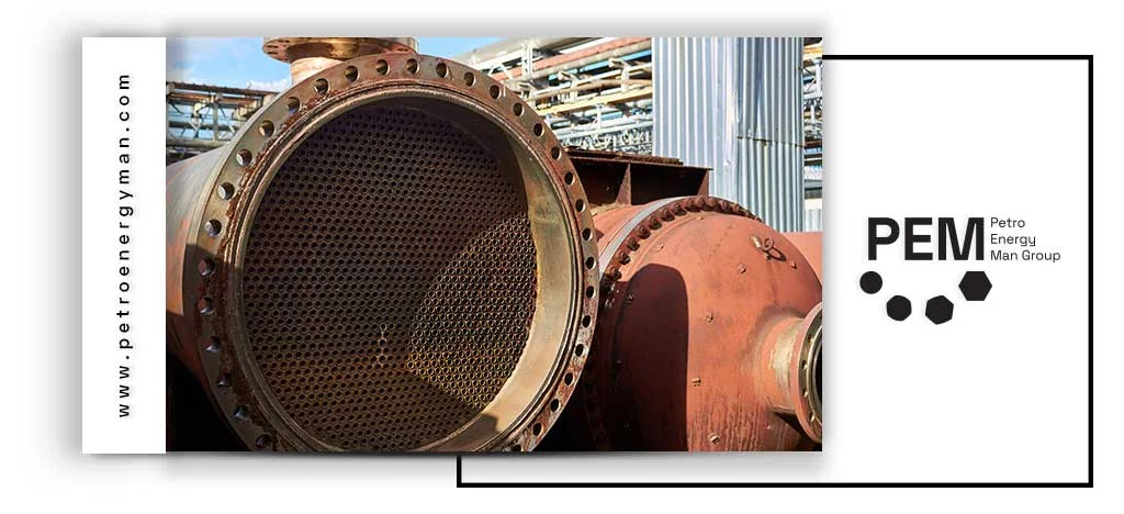
Required Equipment
- Pressure Testing Equipment: Hydrostatic and pneumatic test pumps, calibrated pressure gauges, high-pressure hoses, test rings, and blind plates.
- Tracer-Based Testing Equipment: Helium mass spectrometer for precise leak detection, UV flashlight, and yellow safety glasses for fluorescent leak detection.
- Non-Destructive Testing (NDT) Equipment: Eddy current testing devices with array probes, ultrasonic testing devices with thickness measurement probes, and acoustic emission monitoring systems.
Leak Repair Methods
- Plugging: The most common method for damaged tubes is to block them using plugs. This allows the heat exchanger to continue operating with fewer tubes, though it will result in reduced thermal efficiency.
- Re-Rolling: If the leak originates at the tube-to-tubesheet joint, the connection can be tightened by re-rolling with specialized tools.
- Welding: Where possible, cracks or holes in accessible tubes or areas can be repaired by welding.
If the number of plugged tubes reaches a level where the heat exchanger’s efficiency is significantly compromised, a Retube (complete replacement of the tube bundle) becomes necessary.
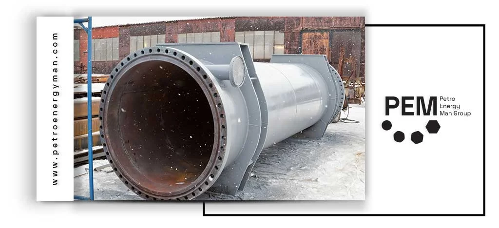
Conclusion
Leak in shell and tube heat exchanger occurs due to various factors. Inspectors start with root cause analysis and visual inspections, then perform pressure tests, tracer-based methods, and advanced NDT techniques. Operators must follow strict safety protocols, especially during pneumatic tests. Engineers repair identified leaks by plugging, re-rolling, welding, or retubing to maintain efficiency and ensure operational safety.